8
2.
INSTALLATION & OPERATION MANUAL
Your lift is designed for many years of trouble-free service when properly installed &
maintained. Please take the time to read this installation manual before proceeding.
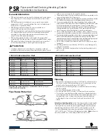
INSTALLATION TIPS
•
This Lift is built from very heavy metal material. User proper lifting techniques when lifting individual pieces. Use
plenty of help when moving lift pieces. It is a good idea to wear work gloves to protect your hands.
•
This lift is designed to be installed on a minimum of 6
”
thick, 3500 psi, wire or fiberglass reinforced concrete. Do
not install this lift on asphalt, wood, or any other surface other than described. A level surface is recommended.
•
Do not install this lift over expansion joints or cracks. Check with your qualified engineer or architect.
•
Do not install lift over a basement or on any level other than ground level (i.e. second floor) without written
authorization from your building engineer or architect.
•
Improper installation can cause damage or injury. Manufacturer will assume no liability for loss or damage of any
kind, expressed or implied, resulting from improper installation or use this product.
•
Read this installation manual in its entirely before attempting to install this lift.
LIFT STRUCTURE INSTALLATION
•
Determine where the lift is to be installed. Make sure there is enough room in front, behind, above and on the sides
of the lift. See (Figure 1) for proper dimensions.
•
Layout with a chalk line your concrete floor to the proper layout you want and check for proper clearances. Se
(Figure 3) for proper dimensions.
•
Remove any loose cables, hoses, part boxes, hydraulic power unit, etc. if they are inside the columns or banded to
the columns.
•
Remove the power unit box, four swing arms from the lift, next remove the bolts holding the two columns together.
Remove the top column from the bottom columns out of the shipping crate and discard the steel.
•
Slide the overhead extensions to the top of each column. Bolt overhead extensions to each column.
•
Stand up the power unit column(the one with power unit bracket welded on it) and position it inside t he chalked
lines to your chalked out dimensions. It is recommended that this column be placed on the passenger side of the car, but it
can go on the driver
’
s side if desired. Keep in mind this is the column where your main electrical power supply will be
connected. The column should face straight toward the other column.
•
Stand up the other column just opposite of the main power unit column inside the chalk lines as shown in (Figure 1).
•
Using a tape measure, measure from back corner to back corner of the base plate to assure columns are square to
each other. Adjust as necessary to obtain best fit and still provide good passage.
•
Now drilling the holes(use 3/4 inch drill bit) for anchors and places anchors as you go. Do not tighten anchor bolts
at this time, Hammer drill all the way through the cement floor.
•
Recheck the level of each column and place horseshoe shims underneath the base plate and around the anchor bolt
wherever they are needed. Tighten 10 anchor bolts and recheck for level and plum. Hammer the anchor bolts all the way
down. Tighten anchor bolts using a torque wrench to 125 ft. / lb. (DO NOT use an impact gun when tightening the anchor
bolts!) 6
”
of embedment is the minimum requirement for reinforced concrete.
•
If you have a straight overhead beam, skip this step. If not, your beam is assembled by two short bars. Bolt two bars
together through one steel sleeve.
Содержание HW-9KOH
Страница 3: ...3 Caution Labeling Exemplification...
Страница 4: ...4 TABLE OF CONTENTS 1 INTRODUCTION 2 INSTALLATION OPERATION 3 MAINTENANCE SAFETY...
Страница 6: ...6 Fig 1 Diagram...