EK76
EK76U Rev A
7
CURRENT SENSE
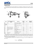
The optional current sense gain and offset circuit is designed to interface with various ADCs in closed-
loop current/torque control. Follow the below schematic and equations to determine the proper component
values.
After assembly of the EK76 including the above Current Sense circuit, R22 must be trimmed to reach the
desired value of V
OS
. To do this, attach a Voltmeter to measure the voltage between pins 11 (negative) and
13 (positive) of P2. Apply the low-voltage supply VCC (+VS should NOT be active). Adjust R22 until the desired
value for V
OS
is shown on the Voltmeter.
The following equation represents the Low-Side Phase Current (I
PHASE
) as a function of voltage measured
at IM_X (V
M
):
Value
Applicable Designators on
EVAL94
Equation
Default
Value
Units
Suggested
Tolerance
V
OS
Bias
ADC min input (or higher)
1.65
V
-
V
OUT_MAX
-
ADC max input (or lower)
3.3
V
-
I
OUT_MAX
-
< 80 A
33
A
-
Gain
-
(V
OUT_MAX
-V
OS
) / (I
OUT_MAX
*
10 mΩ)
5
V/V
-
R
F
R9, 12, 13, 16, 17, 20
1.8k < R
F
< 100k
50k
Ω
0.1%
R
IN
R10, 11, 14, 15, 18, 19
R
F
/ Gain
10k
Ω
0.1%
R
T
R22 (potentiometer)
1k < R
T
< 100k
10k
Ω
-
R
L
R21
Roughly R
T
((V
CC
/2V
OS
) – 1)
39k
Ω
-
C4
C4
C4 = 100n
100n
F
X7R
f
FIL
-
Typically 200k < f
FIL
< 1M
∞
Hz
-
R
FIL
R23, 24, 25
Typically 100 < R
FIL
< 1k
0
Ω
-
C
FIL
C1, 2, 3
1 / (2π * f
FIL
* R
FIL
)
0
F
-
R1-3
10
ŵɏ
R
IN
R
IN
+
-
R
F
R
F
BIAS
R
FIL
C
FIL
IM_X
PGND_X
3X
+
-
1X
BIAS
R
L
R
T
V
CC
C4
PGND
DGND
DGND
Phase
Current
I
PHASE
V
M
V
OS
–
Gain
0.01
---------------------------------
=
Содержание EK76
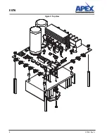
Страница 8: ...EK76 8 EK76U Rev A Figure 2 Top View ...
Страница 9: ...EK76 EK76U Rev A 9 Figure 3 Bottom View ...

