EK76
10
EK76U Rev A
NEED TECHNICAL HELP? CONTACT APEX SUPPORT!
For all Apex Microtechnology product questions and inquiries, call toll free 800-546-2739 in North America. For
inquiries via email, please contact [email protected]. International customers can also request
support by contacting their local Apex Microtechnology Sales Representative. To find the one nearest to you,
go to www.apexanalog.com
IMPORTANT NOTICE
Apex Microtechnology, Inc. has made every effort to insure the accuracy of the content contained in this document. However, the information is
subject to change without notice and is provided "AS IS" without warranty of any kind (expressed or implied). Apex Microtechnology reserves the right
to make changes without further notice to any specifications or products mentioned herein to improve reliability. This document is the property of
Apex Microtechnology and by furnishing this information, Apex Microtechnology grants no license, expressed or implied under any patents, mask
work rights, copyrights, trademarks, trade secrets or other intellectual property rights. Apex Microtechnology owns the copyrights associated with the
information contained herein and gives consent for copies to be made of the information only for use within your organization with respect to Apex
Microtechnology integrated circuits or other products of Apex Microtechnology. This consent does not extend to other copying such as copying for
general distribution, advertising or promotional purposes, or for creating any work for resale.
APEX MICROTECHNOLOGY PRODUCTS ARE NOT DESIGNED, AUTHORIZED OR WARRANTED TO BE SUITABLE FOR USE IN PRODUCTS USED FOR LIFE
SUPPORT, AUTOMOTIVE SAFETY, SECURITY DEVICES, OR OTHER CRITICAL APPLICATIONS. PRODUCTS IN SUCH APPLICATIONS ARE UNDERSTOOD TO BE
FULLY AT THE CUSTOMER OR THE CUSTOMER’S RISK.
Apex Microtechnology, Apex and Apex Precision Power are trademarks of Apex Microtechnology, Inc. All other corporate names noted herein may be
trademarks of their respective holders.
TEST ASSEMBLY
EQUIPMENT NEEDED
1. Power Supplies
2. Digital Controller or 6+ Channel Pattern Generator
3. Oscilloscope
4. Proper Heatsinking System
TEST SETUP
Make sure all supplies are turned off before connection. Connect the power supplies V
CC
(via P15 and
P16) and +V
S
(via P1). See SA310 datasheet for acceptable voltage levels. The +V
S
LED will be visibly bright for
voltages 30V and above. For lower voltages, consider using a smaller-value resistor for R8.
When sequencing power supplies, use the following order:
Power ON: V
CC
, then +V
S
Power OFF: +V
S
, then V
CC
It is recommended to first test the device with no load attached. Ensure the output waveform follows the
expected results before connecting a load. Consider power dissipation in the amplifier, sense resistors, and
the load.
The BNC connectors P3, P4, and P5 are designed for coaxial measurement of the output; these are not
meant to carry significant current. ONLY USE P1 FOR HIGH-CURRENT CONNECTIONS. To use P3-P5, for volt
-
ages within the oscilloscope's input rating, BNC cables may be used to connect directly to the oscilloscope.
For higher voltages, use a high-voltage oscilloscope probe with a probe-tip-to-BNC adapter. Alternatively, use
high-voltage BNC attenuators in series with the BNC cable.
Содержание EK76
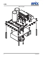
Страница 8: ...EK76 8 EK76U Rev A Figure 2 Top View ...
Страница 9: ...EK76 EK76U Rev A 9 Figure 3 Bottom View ...

