AH-New
condensing air handling unit
APEN GROUP SPA reserves the right to make changes deemed to be required to its products or documentation
30
code HG0310.05GB ed.A-2010
AH
31
code HG0310.05GB ed.A-2010
AH
5.5.
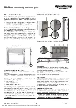
Connections to the Flue
The PCH heater module, contained inside the AH units, is fitted
with a watertight combustion circuit and with the burner fan
located upstream of the heat exchanger.
Connection to the flue, according to how the heater is installed,
can be made as "C" type, with combustion air being drawn from
outside, or as "B" type with combustion air being drawn from
the heater installation site.
If the heater is installed outdoor, a "B" type installation is also
a "C" type.
More specifically, the heater is certified for the following exhausts:
B23P-C13-C33-C43-C53-C63; for more information on the flue
types, please refer to current regulations.
For the flue, certified pipes and terminals must be used, taking
into account that for PCH condensate modules the following
materials must be used:
•
aluminium
•
stainless steel
•
polypropylene (PP)
The pipes and terminal must be certified according to the
Regulation for building products.
Sealed pipes must be used to prevent condensate from leaking
from the pipes; the seal must be adequate to withstand flue gas
temperature ranging between 25°C and 90°C.
The flue does not need to be insulated to prevent the formation
of condensation in the pipe, as this will not affect the heater,
which is fitted with a water trap. Insulate the pipe if required to
protect the flue from accidental contact.
For the air intake, use:
•
aluminium
•
stainless steel
•
polypropylene (PP)
certified according to the Regulation for building products
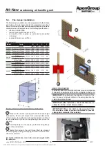
IMPORTANT: The horizontal sections of chimney, which
make up the flue outlet, must be installed with a slight
inclination (1°- 3°) towards the heater, in order to prevent
the build up of condensate in the chimney itself.
Common chimney
Where possible, it is always preferable to use independent
exhausts; AH module exhausts are pressurised, therefore in
this way it is possible to prevent incorrect sizing from causing
a system malfunction.
If you wish to use common flue outlets, there are (OPTIONAL)
KITS on the list “Common flue outlets” pre-sized in stainless
steel as indicated further below in this section.
If you do not wish to use said KITS, the common exhausts
shall be sized by the designer including non-return valves at
the outlet of each flue, before the connection with the common
flue, preventing a module from discharging its own combustion
gases inside another module.
Terminal configuration
B23P type
Open combustion circuit: gases produced by the combustion are
discharged outside, on a wall or on the roof, and the combustion
air is directly drawn from the site where the equipment is installed.
In this case, installation standards require the provision of
suitable vents on the walls.
NOTE: I
t is compulsory to fit on the combustion air
intake an IP20 safety mesh to prevent solids entering
the combustion air intake with a diameter higher than
12mm. The mesh size must be greater than 8mm.
Type C13
Sealed combustion circuit (type "C") connected to a horizontal
terminal on the wall by means of its own ducts.
Type C33
Sealed combustion circuit (type "C") connected to a vertically
installed terminal (on the roof) by means of its own ducts.
Type C53
Sealed combustion circuit (type "C") connected by means of
its own separate ducts to two terminals which can end up in
areas with different pressure (such as a duct connected to the
roof and a second one connected to the wall).
Type C63
Sealed combustion circuit (type "C") connected to an approved
and separately sold combustion air supply and combustion
products exhaust system.


