background image

APEN GROUP SPA reserves the right to make changes deemed to be required to its products or documentation

AH-New 

condensing air handling unit

2

code HG0310.05GB ed.A-2010

AH

3

code HG0310.05GB ed.A-2010

AH

INDEX

SECTION 

1. 

GENERAL CAUTIONS ................................................................. 4


SECTION  

2. 

SAFETY INSTRUCTIONS  ............................................................ 4


2.1 Fuel ............................................................................................................ 4


2.2 

Gas Leaks ................................................................................................. 4


2.3 

Power Supply ............................................................................................ 5


2.4 Use ............................................................................................................ 5


2.5 

Air vents 5


2.6 Installation ................................................................................................. 6


2.7 Maintenance .............................................................................................. 6


2.8 

Transport and handling .............................................................................. 7


2.9 Unpacking .................................................................................................. 8


2.10 

Dismantling and demolition ....................................................................... 8


SECTION  

3. 

TECHNICAL FEATURES  ............................................................. 9


3.1 

Main Components ..................................................................................... 9


3.2 

Technical Data ........................................................................................... 10


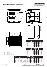
3.3 Dimensions ................................................................................................ 14


3.4 

Air flow rate curves - Available pressure/Power consumption

 ................... 18

SECTION 

4. 

USER INSTRUCTIONS ................................................................. 20


4.1 

AH unit operation ....................................................................................... 20


4.2 

Smart Web

 ................................................................................................. 21


4.3 

Remote On/Off

 .......................................................................................... 23


4.4 

Pressure control ........................................................................................ 24


4.5 

WEB configuration

 ..................................................................................... 26

SECTION 

5. 

INSTALLATION INSTRUCTIONS ................................................. 27


5.1 

General Installation Instructions ................................................................ 27


5.2 Installation ................................................................................................. 27


5.3 

Electrical Connections ............................................................................... 27


5.4 

Wiring to Power Supply ............................................................................. 28


5.5 

Connections to the Flue ............................................................................. 30


5.6 

Condensate drain ...................................................................................... 36


5.7 

Gas Connection ......................................................................................... 37


5.8 

Fire damper installation ............................................................................. 38

SECTION 

6. 

SERVICING INSTRUCTIONS ....................................................... 39


6.1 

Operating cycle .......................................................................................... 39


6.2 

Interface Panel .......................................................................................... 39


6.3 Reset ......................................................................................................... 39


6.4 

Parameters of MASTER and SLAVE modulation PCBs ............................ 40


6.5 

Analysis of Lockouts - Faults ..................................................................... 46


6.6 

Country Table - Gas Category 

 .................................................................. 48


6.7 

Gas Settings Table

 .................................................................................... 49


6.8 

Starting up for the first time

 ....................................................................... 52


6.9 

Combustion Analysis

 ................................................................................. 52


6.10 

Conversion to LPG .................................................................................... 53


6.11 

Conversion to gas G25 - G25.1 - G25.3 - G27 .......................................... 53


6.12 

Conversion to gas G2.350 ......................................................................... 54


6.13 

Replacing the gas valve ............................................................................ 54


6.14 

Replacing the modulation PCB .................................................................. 55


6.15 

Replacing the TER equipment ................................................................... 55

SECTION 7. MAINTENANCE ............................................................................ 56

SECTION 

8. 

LIST OF SPARE PARTS ............................................................... 58

 8

.1 

Parts for control panel ............................................................................... 58


8.2 

Parts for the burner unit

 ............................................................................. 59


8.3 

Other spare parts available

 ....................................................................... 60

Содержание AERMAX AH034

Страница 1: ...mpliant EU 2016 2281 GB Maintenance installation and service manual AH New condensing air handling unit TRANSLATION OF ORIGINAL Manual For Indoor and Outdoor Use NOx Class 5 Yield up to 108 Tax deduct...

Страница 2: ...as 2016 426 CE Gas Appliance Regulation 2016 426 CE Direttiva compatibilit elettromagnetica 2014 30 UE Electromagnetic Compatibility Directive 2014 30 UE Direttiva Bassa Tensione 2014 35 UE Low Voltag...

Страница 3: ...5 INSTALLATION INSTRUCTIONS 27 5 1 General Installation Instructions 27 5 2 Installation 27 5 3 Electrical Connections 27 5 4 Wiring to Power Supply 28 5 5 Connections to the Flue 30 5 6 Condensate dr...

Страница 4: ...e country where the appliance is installed APEN GROUP commercial organisation has an extensive network of authorised Service Centres For any information see Internet site www apengroup com or directly...

Страница 5: ...remain hot for some time after the burner has stopped If the equipment is not to be used for a certain period of time open the main electrical switch of the thermal station and close the manual valve...

Страница 6: ...allation near swimming pools or laundries exposes the unit to the effects of such agents if this is the case we suggest taking air from the outside 2 7 Maintenance Before carrying out any cleaning and...

Страница 7: ...ransport suitable for the shape and for the weight of the load Any lifting and transport operations must be carried out by skilled staff adequately trained and informed on the working procedures and s...

Страница 8: ...g and demolition Should the machine be dismantled or demolished the person in charge with the operation shall proceed as follows Disposal of end of life products This equipment is marked in compliance...

Страница 9: ...agnet electronic motor and high efficiency inverter powered with direct current with integrated rotation speed control All the motors of the centrifugal fans used have the following features Supply 23...

Страница 10: ...equired 6 Connections gas connection UNI ISO 228 1 G 3 4 UNI ISO 228 1 G 3 4 UNI ISO 228 1 G 3 4 Intake exhaust pipes mm 80 80 80 80 80 80 Air flow rate Air flow rate 15 C 5 m3 h 3210 6010 9280 Availa...

Страница 11: ...ISO 228 1 2 x G 3 4 UNI ISO 228 1 2 x G 3 4 UNI ISO 228 1 3 x G 3 4 UNI ISO 228 1 4 x G 3 4 Intake exhaust pipes mm 2 x 80 80 2 x 80 80 3 x 80 80 4 x 80 80 Air flow rate Air flow rate 15 C 5 m3 h 153...

Страница 12: ...00 21 00 360 00 Useful heat output Pmin Prated kW 17 77 148 66 22 77 176 76 22 77 265 14 22 77 353 52 Hi Efficiency N C V pl nom 108 35 97 80 108 40 98 20 108 40 98 20 108 40 98 20 Hs efficiency G C V...

Страница 13: ...96 4 92 5 0 130 0 020 0 005 AH160 160 1 17 8 87 9 97 6 5 0 0 0 28 97 5 93 6 0 246 0 020 0 010 AH210 194 3 22 8 87 5 97 6 5 0 0 0 36 97 4 93 5 0 260 0 020 0 010 AH320 291 5 22 8 87 5 97 6 5 0 0 0 36 97...

Страница 14: ...A L2 LA H2 4 x M8 CARTIGLIO cod X07003 ed 0411 APPROVATO DA D FERRETTI DISEGNATO DA MATERIALE SCALA ApenGroup Heating and Conditioning Solutions DESCRIZIONE 1 15 Quote senza indicazione di tolleranza...

Страница 15: ...003 ed 0411 D FERRETTI DISEGNATO DA MATERIALE SCALA ApenGroup Heating and Conditioning Solutions DESCRIZIONE 1 15 Quote senza indicazione di tolleranza Classe di Tolleranza ISO 2768 M DISEGNO DI PROPR...

Страница 16: ...ry BP LP HP BD1 HD1 LD2 HD2 B2 L2 BA LA LO BV L3 L4 LV AH160 1290 1730 750 1210 670 1210 670 1110 1535 1075 1500 1285 451 1315 186 147 AH210 1290 1730 750 1210 670 1210 670 1110 1535 1075 1500 1285 45...

Страница 17: ...RTIGLIO cod X07003 ed 0411 D FERRETTI Unit T DISEGNATO DA MATERIALE SCALA ApenGroup Heating and Conditioning Solutions DESCRIZIONE 1 20 Quote senza indicazione di tolleranza Classe di Tolleranza ISO 2...

Страница 18: ...0 C T Q nom 35 C T Q nom 30 C AH034 2000 W 10V AH034 800 W 10V 3000 4000 5000 6000 7000 8000 9000 10000 11000 0 100 200 300 400 500 600 700 800 900 1000 m3 h Pa T Q nom 40 C T Q nom 35 C T Q nom 30 C...

Страница 19: ...Q nom 45 C T Q nom 40 C T Q nom 35 C T Q nom 30 C AH105 2000 W 10V AH105 800 W 10V AH080 diagram for AH160 Air flow rate Available Head Pressure Qnom 10 V Air Flow Rate at 15 C m3 h P Pa AH105 diagra...

Страница 20: ...ation AH air handling units feature a CPU modulation PCB inside each module composing them and a wiring card that allows for a simple connection on the user s side and between the modules themselves A...

Страница 21: ...in Priority OFF This setting may be modified directly with the ON OFF key located in the HOME page as shown in the picture 10 15 Mon 01 Jan HOME C 20 7 SET OFF RED System OFF GREEN System ON To switch...

Страница 22: ...erent controls are the following T_SNOW 3 0 C SNOW Contr Not Used SET_SNOW 23 0 C SNOW Contr Not Used SNOW_PREX 200 Pa SNOW Contr Not Used PREX_MIN 90 Pa PRES Contr Not Used PREX_MAX 200 Pa FILTER Con...

Страница 23: ...probe reading error or incorrect probe connection configuration the following condition is present AN3_Ext T_RIF 10 0 By pressing the key next to an input it is possible to access the offset adjustme...

Страница 24: ...he pressure value indicated inside the icon corresponds to the average value of the ventilating section 4 4 Filter control OPTIONAL AH air handling units if purchased with a side or lower optional int...

Страница 25: ...from being damaged due to overheating or the system from stopping Once the initial characteristics of filters and system have been restored press on the FILTER icon in the HOME page of the Smart Web...

Страница 26: ...ible to configure the Smart Web remote control so as to manage it entirely through a PC or other device connected to a private local network Intranet In order to use the Smart Web remotely the network...

Страница 27: ...ed staff that is skilled for the operations required to start it Condensate drain The air handling unit is supplied with water trap to drain the condensation Thewatertrapisanintegralpartoftheequipment...

Страница 28: ...live wire GROUND wire is mandatory Connect it to the relevant PE terminal The air handling unit must be correctly connected to an effective earthing system fitted in compliance with current legislati...

Страница 29: ...age cables can be housed in the same conduit by using double insulated cables HG0103_C2 021 Low voltage cable High voltage cable Pipe or conduit NO YES Useflexible flame retardant double coatingcables...

Страница 30: ...installed with a slight inclination 1 3 towards the heater in order to prevent the build up of condensate in the chimney itself Common chimney Where possible it is always preferable to use independent...

Страница 31: ...y as indicated in the following table For AH VERTICAL UnitI xxV0 Model INDEPENDENT flue outlet kit aluminium COMMON flue outlet kit stainless steel Code Code AH034xx xxV0 G18165 105 Not available AH06...

Страница 32: ...O cod X07003 ed 0411 MODIFICA APPROVATA DA APPROVATO DA DATA MODIFICA MODIFICA DISEGNATA DA DESCRIZIONE MODIFICA ESP DATA DISEGNATO DA Materiale non specificato MATERIALE SCALA ApenGroup Heating and C...

Страница 33: ...IZIONE 1 15 Quote senza indicazione di tolleranza Classe di Tolleranza ISO 2768 M DISEGNO DI PROPRIETA APEN GROUP spa E VIETATA LA RIPRODUZIONE E LA DIFFUSIONE ANCHE PARZIALE SENZA L AUTORIZZAZIONE DE...

Страница 34: ...icazione di tolleranza Classe di Tolleranza ISO 2768 M DISEGNO DI PROPRIETA APEN GROUP spa E VIETATA LA RIPRODUZIONE E LA DIFFUSIONE ANCHE PARZIALE SENZA L AUTORIZZAZIONE DELL APEN GROUP spa ISO 2768...

Страница 35: ...ura con dimensioni fino a 100mm ISO 2768 C 1166 79 PESO G A2 FOGLIO HG0310 00_XX 0016 TYPE OF GAS G20 Cat E H TYPE OF MACHINE AH034 AH065 AH105 AH160 AH210 AH320 AH420 Output min max min max min max m...

Страница 36: ...According to the type of installation the module can drain the condensate in the following ways free drainage drainage in drain wells drainage inside water traps AH air handling units are supplied wit...

Страница 37: ...r with great capacity since the filter supplied as standard upstream of the gas valve has a limited surface IMPORTANT For proper maintenance connect the AH module by means of a seal and swivel gasket...

Страница 38: ...G23766 1670 800 510 35 AH420 Delivery G23746 1400 1370 510 35 Horizontal Intake Vertical Intake G23776 1670 800 510 35 USE OF FIRE DAMPER Toactivatethedamperrotatethecontrollevercounter clockwise To...

Страница 39: ...e exchanger will cause a shorter lifetime of the exchanger and the guarantee will be null and void the safety thermostat to operate and the associated requirement to manually reset the heater IMPORTAN...

Страница 40: ...10 50 500rpm 0 300 b6 2 sec 20 Error F3x error dwell time before fault F3x 0 255 b7 2 sec 20 Pre cleaning time with maximum output 0 255 DO NOT CHANGE THE PRESET VALUE b8 2 sec 10 Flame stabilisation...

Страница 41: ...Y2 enabled 0 10Vdc 3 outputs Y1 PWM and Y2 0 10Vdc enabled 4 outputs Y1 PWM and Y2 0 10Vdc enabled for pressostatic structures 5 analogue output Y2 0 10Vdc enabled for operating mode d1 10 12 6 output...

Страница 42: ...sure control analogue input with F80 fault auto reset 6 enabled read only no Fault for pressure control via Modbus ST5 1 mbar 1 2 B2 setpoint 0 9 99 setpoint sent by the Smart Web P5 2 mbar 0 5 ST5 hy...

Страница 43: ...st active in Fault in case of heat request Burner parameters b1 2 rpm 210 182 195 172 195 195 195 Motor RPM MINIMUM value PWM1 90 999 1 10 RPM b2 2 rpm 710 651 635 655 635 635 635 Motor RPM MAXIMUM va...

Страница 44: ...modulation 1 modulation and ON OFF TH1 2 C 85 Upper Temperature limit for fault F51 activation 10 95 autoreset if NTC1 TH1 15 C S3 2 1 NTC3 probe enabling 0 disabled 1 enabled TH3 2 C 85 Upper temper...

Страница 45: ...s only output Y2 H17 3 1 0 PWM Y1 or 0 10V Y2 output according to direct logic 1 PWM Y1 or 0 10V Y2 output according to reverse logic 2 PWM Y1 reverse and 0 10V Y2 direct output 3 PWM Y1 direct and 0...

Страница 46: ...ipment lockout It indicates that if the heat request has remained active for more than 24 consecutive hours the TER equipment has performed a control cycle switching temporarily to stand by mode Manua...

Страница 47: ...esolve No voltage F75 No voltage during operation cycle excluding stand by the fault is not visible on remote control but only counted No voltage during operation Auto resolve F80 Pressure gauge error...

Страница 48: ...t the factory settings NOTE In compliance with standards EN17082 EN 437 and ISO3166 GB refers to the United Kingdom Codes with no extension AH105IT if there is no extension it means that the equipment...

Страница 49: ...reference table SUPPLY PRESSURE mbar 25 min 17 max 30 PILOT NOZZLE mm 1 x 0 7 1 x 0 7 1 x 0 7 2 x 0 7 2 x 0 7 3 x 0 7 4 x 0 7 GAS CONSUMPTION 15 C 1013mbar m3 h 0 93 4 29 1 53 8 00 2 21 12 30 2 02 20...

Страница 50: ...2 21 49 16 CARBON DIOXIDE CO2 CONTENT 9 1 9 6 9 3 9 7 9 4 9 6 9 8 10 3 9 4 9 6 9 4 9 6 9 4 9 6 FLUE GAS TEMPERATURE C 31 94 31 86 28 80 26 70 28 80 28 80 28 80 GAS ORIFICE PLATE mm 1 x 8 9 Not requir...

Страница 51: ...mm Not required Not required Not required Not required Not required Not required Not required 1 Minimum rated heat input 24 kW 2 Minimum rated heat input 36 kW 3 Minimum rated heat input 48 kW 4 Mini...

Страница 52: ...n the Von value on the LCD display When ON appears on the LCD display the heater starts the ignition cycle NOTE Frequently when turned on for the first time the pilot burner cannot ignite because ther...

Страница 53: ...replace the nameplate indicating Equipment regulated for natural gas with the one in the kit that indicates Equipment converted 6 11 Conversion to gas G25 G25 1 G25 3 G27 ConversionforgassesfromG20toG...

Страница 54: ...ype of gas If the value is different change it by turning the adjustment screw on the Venturi pipe screwing it down decreases the value loosening it increases the value Stick the nameplate Equipment c...

Страница 55: ...meters mentioned inthetableinparagraph6 4 Modulation PCBparameters must be necessarily reprogrammed except the parameters marked as NOT USED Programming the parameters Operating mode Parameterscanbemo...

Страница 56: ...of the gas valve Should it become necessary to clean the burner and or exchanger allthegasketsbetweentheburnerandtheexchanger must be replaced NOTE To ensure a correct sealing of gaskets the nuts of...

Страница 57: ...rent This procedure can be done directly from the LCD display by entering into the I O menu The IOn parameter indicates the value of the ionization current and the reading is as follows 100 indicates...

Страница 58: ...10054 ON OFF Connector G10051 ALARM Connector G10052 CPU SMART PCB G16800 03 ModBus Connector G10054 NTC1 Connector G04763 0 10Vdc Connector G10052 Burner Fan Power Supply Connector G10053 Electrical...

Страница 59: ...G Gas valve G14456 For all models Air gas fan G22903 PCH020 034 G22904 PCH045 065 G22815 PCH080 G22816 PCH105 Gas valve Venturi G14898 PCH020 G14990 PCH034 G16219 PCH045 G14154 PCH065 080 G14154 08PCH...

Страница 60: ...DDMP fans G18652 10 10 EC 2000W 1x AH034 2x AH105 4x AH160 AH210 6x AH320 8x AH420 G18654 10 10 EC 800W 1x AH034 2x AH105 4x AH160 AH210 6x AH320 8x AH420 G18655 10 8 EC 2000W 2x AH065 G18651 10 8 EC...

Отзывы: