
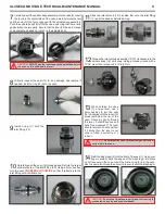


NOTE
:
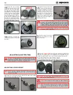
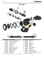
Check the spring carrier (21) for a small o-ring (19) that
should be removed. If no o-ring is present, check inside the shuttle
valve (18) for the o-ring.
16
Confirm the o-ring (19) is removed from the spring carrier
(21). If it cannot be found, make sure to look inside the shuttle
valve (18).
NOTE
:
There is no need to
remove the micro adjuster
screw (23) from the spindle
adjuster sleeve (22).
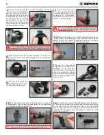
17
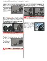
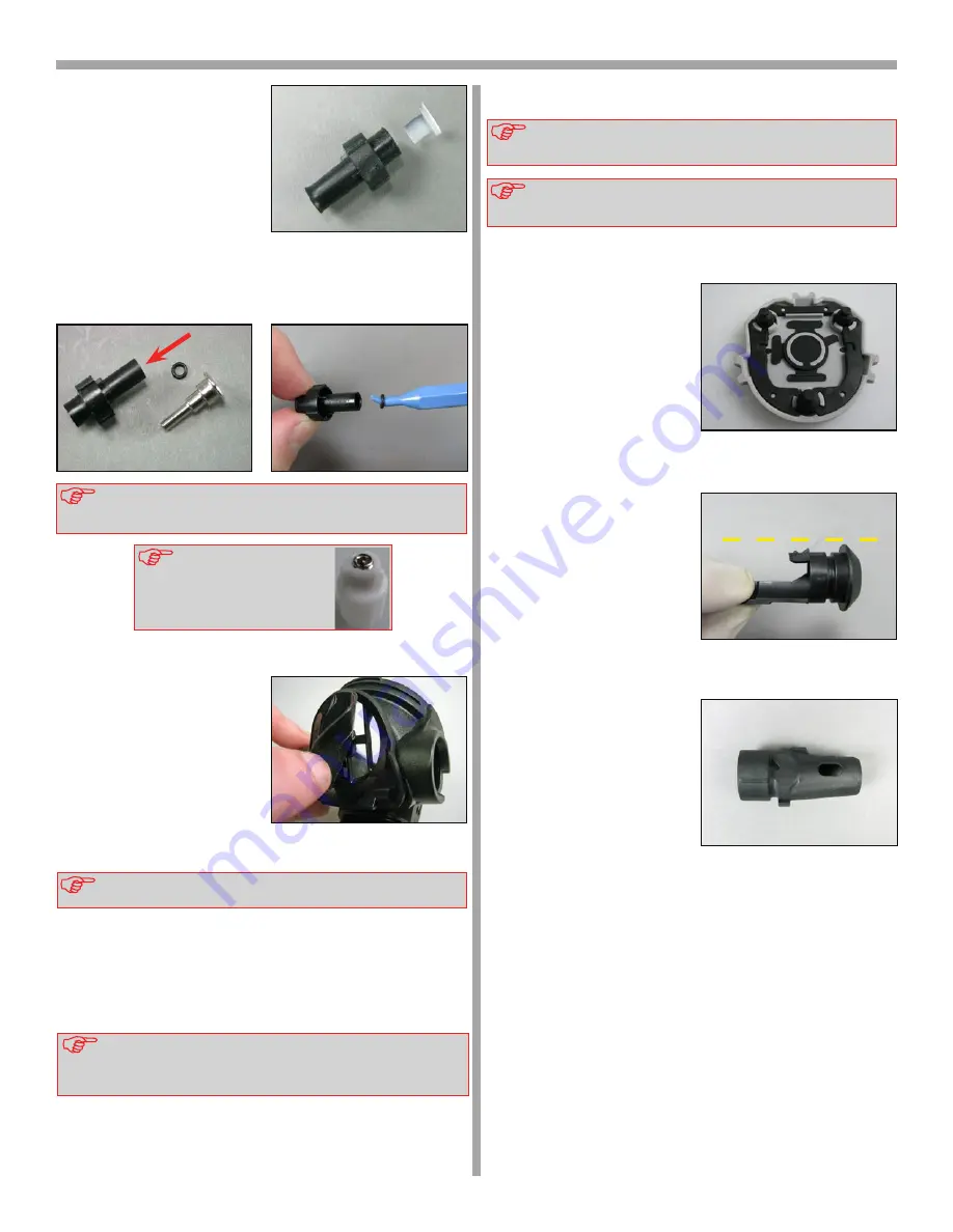
Fold back the edges of
the exhaust valve (25)
and inspect underneath. The
seating surface should be clean
and free of damage. Inspect
the exhaust valve, it should be
supple and have well defined
edges. If it looks good, there is
no need to remove it and may
be reused. If there is any sign
of deterioration, it should be
replaced.
NOTE
:
If the exhaust valve (25) is to be removed, pinch the edge
of the valve and pull the tail through the hole in the case (7).
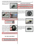
THIS ENDS DISASSEMBLY
NOTE
:
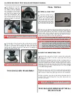
The following parts should be checked for cracks, deep
scratches, excessive wear and tear and distortion. Sealing faces,
grooves and bores should be checked for scratches.
INSPECTION PROCEDURE
NOTE
:
Before performing any reassembly procedures, there are
several parts that must be inspected. The following section details
the parts and areas that must be checked.
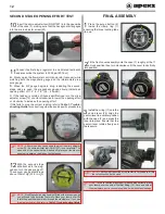
1
Inspect the back face of the
front cover assembly (2).
Check that the rubber purge
spring is firmly located around
the entire perimeter of the front
cover.
2
Check that the tab of the
venturi lever (24) has not
been over stressed and that it
is level with the rest of the lever.
3
Check that the spindle body
(16) is free from scratches,
cracks and distortion. Look for
excessive wear around the lever
holes. Check that the thread is
in good condition.
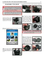
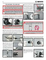
NOTE:
Before beginning reassembly, perform
parts cleaning and lubrication in accordance with
Procedure A: Cleaning and Lubricating.
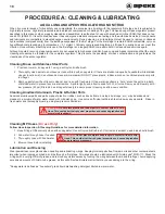
15
Using your fingernail,
remove the MP seat (17)
from the shuttle valve (18).
7
XL4 SECOND STAGE TECHNICAL MAINTENANCE MANUAL


