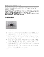
background image

ZONE4R


connector


and


wiring


details:


1.


Ground


connection


(GND)

 ‐

>


connect


to


RJ45


pin


1


and


3


and


7


(colours


:


see


table


below)


2.


Data


connection


(Rx


B)

 ‐

>


connect


to


RJ45


pin


4


(colours


:


see


table


below)


3.


Data


connection


(Tx


A)

 ‐

>


connect


to


RJ45


pin


5


(colours


:


see


table


below)


4.


Power


supply


(+12VDC)

 ‐

>


connect


to


RJ45


pin


2


and


6


and


8


(colours


:


see


table


below)


RJ45


connections


on


rear


of


ZONE4


main


unit


‘to


zone


remote


wall


panels’


:


Æ


Æ


Pin


number


RJ45


T

568A


cable


colour


code

T

568B


cable


colour


code

Euroblock


4


(see


picture


above)

Pin


1


:


GND


white


green


white


– orange

connector


1


Pin


2


:


12


VDC


green


orange

connector


4


Pin


3


:


GND


white


orange


white


– green

connector


1


Pin


4


:


Rx


B


blue


blue

connector


2


Pin


5


:


Tx


A


white


blue


white


– blue

connector


3


Pin


6


:


12


VDC


orange

green

connector


4


Pin


7


:


GND


white


brown


white


– brown

connector


1


Pin


8


:


12


VDC


brown


brown

connector


4


Содержание ZONE4R

Страница 1: ... the knob to mute the music the mute status is indicated by led 4 2 Display this shows the selected music line source A to D or the music or microphone levels When a value has been edited the display lights up more strongly during a few seconds After a few seconds the display will show the selected music source again Please note that after some time of non operation the intensity of the display wi...

Страница 2: ...s see table below RJ45 connections on rear of ZONE4 main unit to zone remote wall panels Æ Æ Pin number RJ45 T 568A cable colour code T 568B cable colour code Euroblock 4 see picture above Pin 1 GND white green white orange connector 1 Pin 2 12 VDC green orange connector 4 Pin 3 GND white orange white green connector 1 Pin 4 Rx B blue blue connector 2 Pin 5 Tx A white blue white blue connector 3 P...

Страница 3: ...You can connect multiple ZONE4R units to the ZONE4 main unit using a straight through CAT5 cable hub You can assign multiple ZONE4R units to the same zone The maximum number of ZONE4R units connected to a single ZONE4 unit is 8 pieces Maximum approved CAT5 cable length is 100 meters per zone ZONE4R zone select switch at the back of the ZONE4R unit ZONE4R optional accessories RJ45SPLIT 1 in 4 out s...

Страница 4: ...8A or T 568B are possible For details about wiring please refer to the wiring details and colour code T 568B termination is not recognized in the USA but is considered as standard cable termination in many other countries Dimensions Front plate dimensions 114 x 80 mm Mounting hole spacing 83 mm Cutout dimensions without using a backbox 70W x 55H mm mounting depth 40 mm ...

Отзывы: