APAR AR602.B Скачать руководство пользователя страница 18

18 

the output operating in the retransmission mode enables the conversion of the input signal to the output signal 

(in the range 

ArLo


÷


ArHi

 ). In the control output mode, the control parameters and functions are the same as for 

the related output 1/2/3, but the variability range of the analog signal is continuous (0 ÷ 100%) only for the PID 
algorithm (

chapter 9.3

) and manual operation, for the control of ON-OFF type with hysteresis, the output has 

extreme values (bottom or upper value, e.g. 0mA = 0% = OFF or 20mA = 100% = ON) without intermediate values, 
which can be used e.g. to activate the SSR relay.  
The values of the output signal (mA/V) can be presented in the form of a bargraph on the bottom line of the 

display (parameter 73: 

dibo

 = 

bArA

) or read from the level of MODBUS-RTU/TCP and MQTT protocols, 

chapter 11

Moreover,


it is


possible to


correct


(calibrate) the


range of


changes of the


output signal


(parameters 34: 

cbot


and 

35: 

ctoP

). 


9.3. PID CONTROL


The PID algorithm makes it possible to obtain smaller temperature 
control errors than the ON-OFF method with hysteresis. However, 
this algorithm requires selection of parameters characteristic for a 
specific regulation object (eg a furnace). In order to simplify the 
handling, the controller is equipped with advanced functions of PID 
parameter selection, described in 

chapter 9.4

. In addition, it is always 

possible to manually adjust the settings (

chapter 9.5

). 

The PID control for a given control output is active when one of the 
three sets of PID parameters is selected (with the parameter 

ctY1

/

2

/

3


, description in chapter 8, Table 8, point II

, or with the 

parameter 

PSE1

/

2

/

3

,


point V

), i.e. 

PiD1

/

2

/

3

.  

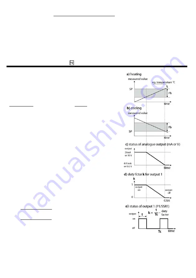
The position of the proportional band 

Pb

 (

Pb1

/

2

/

3

Table 8, point IV

in relation to the setpoint 

SP

 (

SEt1

/

2

/

3

) is shown in Figures 9.3 a) 

and b). The parameters 

ti1

/

2

/

3

and 

td1

/

2

/

3

 are responsible for the 

influence of the integral and derivative element of the PID control. 

The parameter 

PEr1

/

2

/

3


sets the pulse period 

Tc

 for the P/SSR 

output (it is also the time of its status update), while 

oPF1

/

2

/

3

 the


available power used for selecting PID parameters. If the PID 
algorithm is implemented by the 0/4 ÷ 20mA or 0/2 ÷ 10V analog 
output, the 

Tc

 period is irrelevant. The mA/V output signal is then 

updated every 1 s and it can adopt intermediate values from the 
entire range of output variability (0÷100%). 
The principle of operation of the P-type control (proportional 
control) for the P/SSR output is shown in figures d), e) for the analog 
output, figure c). 

Fig. 9.3.

 Principle of PID regulation operation: 

a)

 position of the 

Pb

 proportional band in relation to the setpoint 

SP


for the heating type control (

Fvn1

/

2

/

3

 = 

indH

 ) 

b)

 position of the proportional band 

Pb

 in relation to the setpoint 

SP


for the cooling type control (

Fvn1

/

2

/

3

 = 

dirC

c)

 the status of the analog output 0/4÷20 mA or 0/2÷10V 

d)

 duty factor 

k

 for a bi-state P/SSR output 

e)

 the status of the output for the measured value 

PV

 within the 

Pb


range 


Содержание AR602.B

Страница 1: ...yn ul Ga czy skiego 6 tel 22 101 27 31 853 48 56 853 49 30 e mail automatyka apar pl www apar pl USER MANUAL AR602 B AR652 B AR642 B AR682 B AR632 B AR662 B UNIVERSAL PROGRAMMABLE CONTROLLERS Version...

Страница 2: ...SETPOINTS FOR OUTPUTS QUICK ACCESS MENU 17 9 2 ANALOG OUTPUT mA V 17 9 3 PID TUNING 18 9 4 AUTOMATIC SELECTION OF PID PARAMETERS 19 9 5 PID PARAMETERS CORRECTION 20 9 6 PROGRAMMED WORK CHARACTERISTIC...

Страница 3: ...F CONTROLLERS ACCESSORIES AND KIT CONTENTS control and supervision of temperature and other physical values humidity pressure flow level velocity etc converted into a standard electrical signal config...

Страница 4: ...input type range of indications for analogue inputs options of control alarms display communication access and other configuration parameters access to configuration parameters protected by a user s...

Страница 5: ...ure 0 1 C or 1 C programmable with parameter 3 dot Indications range resolution for analog inputs maximum 1999 9999 programmable Decimal point position for analog inputs programmable 3 dot in the rang...

Страница 6: ...ply circuit and relay outputs 50 V for the remaining input and output circuits and communication interfaces insulation resistance 20 M altitude above the sea level 2000 m 5 HOUSING DIMENSIONS AND ASSE...

Страница 7: ...input universal 14 15 16 P1 or SSR1 relay output 14 15 for AR602 B P2 or SSR2 output 14 15 17 18 P2 or SSR2 relay output for AR602 B P1 or SSR1 output 19 20 P3 or SSR3 relay output except AR602 B USB...

Страница 8: ...on the display board and carefully slide the board out of the mounting sockets connectors for signal cables power supply and relay outputs are available lead the electric wires into the housing throu...

Страница 9: ...5s chap 7 1 and 8 F not available in AR602 B activation of the function selected with parameter 64 FunF pressing longer than 1 5 seconds description in chapters 7 1 and 8 UP DOWN SET simultaneously o...

Страница 10: ...ive level short circuit or 0 8V Moreover BIN has priority higher than the F and SET keys Activating or stopping the function is signaled by appropriate messages on the lower display described in Table...

Страница 11: ...ault value of a parameter description of the function in chapter 7 points b and c confirm the changed value of the parameter with the SET key or cancel it with the F or UP DOWN keys pressing UP DOWN o...

Страница 12: ...or the bottom of the indication range 99 9 1800 lower setting limit for setpoints SP 11 Set1 Set3 99 9 C 999 9999 2 beginning of the scale for the 0 4mA 0V 0 input and the PV bargraph 5 irHi upper lim...

Страница 13: ...D software main output STB LATCH and step adjustment servo 2 for PID software main output and servo algorithms only heating inversed and cooling direct characteristics apply 3 Values 4 7 i e in relati...

Страница 14: ...Fto1 2 3 output emergency state for missing damaged sensor signal input or outside the measuring range 0 noCh no change 1 oFF disabled 2 on enabled 3 hAnd manual mode with a set output signal level pa...

Страница 15: ...0 units min 2 1 0 C min 50 55 60 tiM1 2 3time for stage 1 2 3 0 1440min duration of the segment for the stage with countdown 60 min 51 56 61 PSE1 2 3control algorithm for step 1 2 3 1 onof ON OFF with...

Страница 16: ...graph for mA V output 8 barP PV bargraph measurement in the range irLo 5 irHi con1 VIII COMMUNICATION OPTIONS FOR RS485 AND ETHERNET submenu trAn description in chapters 11 11 5 74 r4br speed for RS48...

Страница 17: ...possibilities offered by the program control chapter 9 6 A detailed description of configuration of the operation of outputs is included in chapters 9 1 9 7 The default factory configuration is as fol...

Страница 18: ...adjust the settings chapter 9 5 The PID control for a given control output is active when one of the three sets of PID parameters is selected with the parameter ctY1 2 3 description in chapter 8 Table...

Страница 19: ...ng sudden changes of the measured value PV or the setpoint SP The choice of the parameter selection method depends on the nature of the initial conditions For a stabilized controlled quantity the step...

Страница 20: ...stage 1 2 3 operates in accordance with the control parameters of the assigned setpoint SP 1 2 3 description in Table 8 point II A program can be assigned to any of the control outputs 1 2 3 with para...

Страница 21: ...period for output 2 parameter 21 Per2 Sample configuration ON OFFfor heatingwith a set temperature of 50 C and a valve opening closing time of 100s output 1 parameters Table 8 point II group out1 ctY...

Страница 22: ...mode on off F SET BIN function chapter 7 1 Pr 1 2 3 PEnd process controller function ramping on output 1 2 3 chapter 9 6 Stb1 2 3 STB LATCH alarm for outputs 1 2 3 cleared by F SET BIN with the functi...

Страница 23: ...es not block the ports and applications used e g ARSOFT CFG The unique MAC EUI 48 hardware address of the controller Ethernet interface is available in ARSOFT CFG Parameters Communication options and...

Страница 24: ...arameters used by this service such as the TCP port number are described in chapter 8 Table 8 point VIII The timeout for the MODBUS TCP transmission after which the open but unused port is closed is 6...

Страница 25: ...evice function 4 or 3 register address to be read from Table 11 5 chap 11 5 number of registers to be read 1 13 CRC checksum 1 byte 1 byte 2 bytes HB LB 2 bytes HB LB 2 bytes LB HB Example 11 4 1 Read...

Страница 26: ...status of outputs alarms 1 2 3 bits 0 1 2 bit 1 output enabled STB LATCH alarms for outputs 1 2 3 bits 3 4 5 bit 1 active quick manual mode for outputs 1 2 3 bits 6 7 8 bit 1 active PID tuning status...

Страница 27: ...net interface EUI 48 Configuration parameters the collective list of parameters can be found in chapter 8 Table 8 Register parameter address 35 parameter index from Table 8 e g address 35 for paramete...

Отзывы: