background image

17 

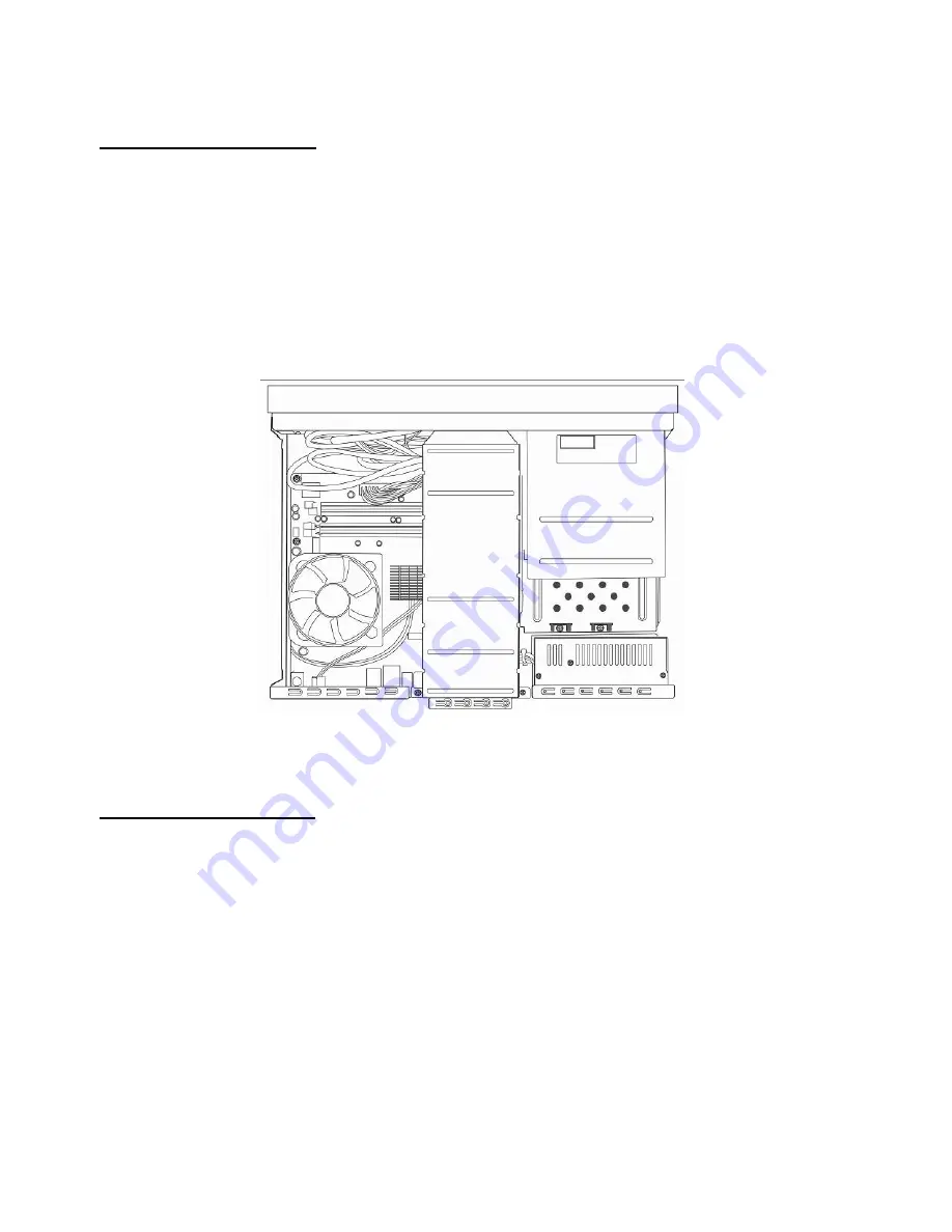
Remove the CPU Cooler 

Your system may come with or without a CPU cooler depending on the various 

configurations marketed by your distributor. The CPU cooler is fixed to the motherboard 

with four screws. Removing the screws with a screw driver with magnetic tip will make 

the job a lot easier.   

Detach the 4-pin CPU fan power cable from its connector on the motherboard.     


Begin to Install the CPU 

To install the CPU, you have to remove the CPU plastic protective cap first. You have to 

press the steel CPU socket lever down and move it sideways to release the L-shaped lever. 

The plastic CPU cover will come off. 


Содержание EPC945-M8

Страница 1: ...les on the backboard of the computer case to dissipate heat from the machine You should pay attention to the position of the PC so that the ventilating holes will not be blocked Meanwhile do not put your PC on something not sturdy enough like rug or bed mattress to ensure smooth air flow for heat dissipation 6 Before plugging on power make certain the electric voltage in your area complies with th...

Страница 2: ...nce personnel so as to avoid improper disassembling 10 When encountering the following more dangerous situations unplug the power to shut down the system and then seek help from professional technicians to fix the problems When liquids find their way into the equipment When the PC is soaked by rain When power cords or power sockets are damaged When the PC system falls to the ground and is damaged ...

Страница 3: ...ndation When replacing battery use the battery which conforms to the manufacturer s specifications When disposing the batteries dispose the batteries to a recycle center which is designated by your local authority to process batteries Follow all your local authority s safety and waste disposal regulations in disposing the batteries Safety Caution Concerning Laser Products This equipment built with...

Страница 4: ...move the Link Bar 16 Remove the CPU Cooler 17 Begin to Install the CPU 17 Install CPU on Socket T 18 Install CPU to Socket 754 19 Install CPU to Socket 479 20 Install CPU to Socket 939 22 Install Memory Modules 22 Disassemble Optical Disc Drive 22 Install Optical Disc Drive 24 Disassemble Hard Disc Drive 27 Lift the Drive Cage 28 Install Hard Disc Drive 28 Chapter 3 Turn on the Power 30 Appendix 3...

Страница 5: ...orp With the MCE a user can turn the system unit into a Media Center PC and his her home into a digital entertainment center Features 1 The product is the first smallest ViiV desktop ePC with a size of 430 x 89 x 300 mm 2 The system is built with Intel 130W dual core CPU 945G ICH7DH chipset and Intel LAN technology 3 It is designed to be the first smallest ViiV desktop ePC in compliance with VCR s...

Страница 6: ...nd digital audio SPDIF input and SPDIF output 11 The first smallest ViiV desktop ePC that supports DMA and ViiV platforms and 1080i high definition TV output which enables large screen TV display sharp images Unpacking Your System Upon unpacking your system you will see the following items 1 Power cable 2 A remote control 3 Two AA type battery 4 7 1 channel audio cable 5 2 channel RCA adaptor 6 S ...

Страница 7: ...locate other indicators such as HDD Record and remote control indicators The infrared censor for the remote control is located below the remote control indicator USB 2 0 Card Reader Located next to the optical disc drive is a USB 2 0 23 in 1 memory card reader A user can open the cover of the memory card reader by pushing the upper right corner of the cover Power Card Reader Optical Device Eject B...

Страница 8: ... MMC1 MMC2 MMC4 0 1 bit z Secure Digital Card z MS MS MG z MS PRO MS PRO MG z Memory Stick ROM z MS Select z XD with adapter z MS Duo MS Duo MG z MS PRO Duo MS PRO Duo MG z Mini SD z RS MMC z T flash Slot 2 Compact Flash Card type I Compact Flash Card type II IBM Micro drive ...

Страница 9: ...the input output I O connectors power switch and power source connector on the rear panel These I O ports include the connectors for PS2 keyboard and mouse the printer parallel port VGA USB 2 0 IEEE 1394 LAN and COM ports Worldwide Volume Next Previous Stop Eject Play Pause USB 1394 Phone MIC SPDIF Out 7 1 ch Audio LAN USB VGA COM1 Keyboard Add2 Card DVI out S video connect to red head Composite o...

Страница 10: ...t the same time the display screen will not work properly Europe 7 1 ch Audio LAN USB VGA COM1 Keyboard Add2 Card DVI out S video connect to red head Composite out connect to yellow head Y Pb Pr D4 out Japan only COAXIAL 7 1 ch Audio LAN USB VGA COM1 Keyboard Add2 Card DVI out COAXIAL SCART out Europe only Mouse Mouse ...

Страница 11: ... rating selection switch on the rear panel You should use that slide switch to select the appropriate power rating In case your system comes with a 375W power supply there is no need for manual selection The power supply will select the power rating intelligently Voltage selector ...

Страница 12: ...put of a TV set The DVI output of the ADD2 video card allows a user to connect to an LCD video display monitor with DVI interface The ADD2 video card is installed to one of the expansion slot in Burgundy color on the motherboard Near the top edge of the ADD2 video card there is a 10 pin female connector for the D4 cable which is an option for the users in Japan For the users in Europe the system m...

Страница 13: ...ast Forward 8 REPLAY Replay 9 SKIP Skip to the next chapter 10 BACK Back to the previous chapter 11 MORE Information 12 ARROW KEYS Left Right Up and Down arrow keys 13 OK Confirmation on selection 14 Volume Up Increases the audio volume 15 Volume Down Decreases the audio volume 16 START Launch MCE main menu 17 Channel Up Changes the channel to the next higher channel 18 Channel Down Changes the ch...

Страница 14: ...14 21 RECORD TV TV recording 22 GUIDE Guide information 23 LIVE TV TV mode 24 DVD MENU Display DVD menu 25 Alphanumer ic keys Enter alphanumerical letters 26 CLEAR Clear input 27 ENTER Confirm input ...

Страница 15: ...top cover 2 Remove the link bar 3 Remove the CPU cooler Remove the Top Cover A user can disassemble the upper case by removing the two screws on the two sides of the rear panel After removing the screws pull the top cover horizontally about 1 cm 0 394 inch toward the rear panel and then lift the top cover upwards ...

Страница 16: ...16 Remove the Link Bar Three screws fasten the link bar to the chassis Remove the three screws Lift the link bar by pulling up its end near the rear chassis ...

Страница 17: ...ws Removing the screws with a screw driver with magnetic tip will make the job a lot easier Detach the 4 pin CPU fan power cable from its connector on the motherboard Begin to Install the CPU To install the CPU you have to remove the CPU plastic protective cap first You have to press the steel CPU socket lever down and move it sideways to release the L shaped lever The plastic CPU cover will come ...

Страница 18: ... 1 Remove plastic cap and lift CPU socket lever 2 Lift CPU socket plate and install CPU to CPU socket Then press plate back to cover the CPU socket 3 Press down CPU socket lever to finish CPU installation Lever Plastic Cap Plate ...

Страница 19: ...19 Install CPU to Socket 754 1 Lift CPU socket lever and gently install CPU to its socket 2 Press lever back to CPU socket to finish the installation Lever ...

Страница 20: ... sure the drop shaped indicator on socket screw aim at open direction the default is open 2 Match socket Pin 1 and golden arrow and gently install CPU to its socket Then lock socket screw clockwise to finish CPU installation Plastic membrane Socket screw Golden arrow Socket pin 1 ...

Страница 21: ...21 Install CPU to Socket 939 1 Lift CPU socket lever and gently install CPU to its socket 2 Press lever back to CPU socket to finish CPU installation ...

Страница 22: ...incorrectly The notch should match an extruding point of the memory socket Press down the memory modules into the slots and lock them onto the slots with the clasps on two sides of the slots Disassemble Optical Disc Drive Your system may come with or without an optical disc drive which is fixed to the drive cage with three screws on its sides ...

Страница 23: ...e power and flat cables connected to the optical device Remove the screws using an appropriate screw driver Slide the optical device toward the rear of the chassis Once the optical device is moved clear of the front edge of the front panel lift it up vertically ...

Страница 24: ...panel of the system locate two screw holes near the top of the optical disc drive We will refer to this side as the left side of the optical device hereafter Fasten the two screws which are designed specially for fixing the optical disc drive to the drive cage Place the optical disc drive into the drive cage ...

Страница 25: ...e have to slide into the slits on the side of the drive cage As you slide the optical device toward the front panel you should be able to see the screw holes on the right side of the optical device appearing on the side of the drive cage There are five Arabic numerals 1 2 3 4 and 5 on the lower right corner of the drive cage Slide the optical drive until the lower screw hole aligned with the Arabi...

Страница 26: ...he black tab to optimize its position Note 2 When you install the optical drive make sure that you don t push the drive all the way toward the front panel so that the black tab is too close to the real Eject button on the optical drive If the optical drive is too close to the black tab it will cause the optical drive to eject the disc tray all the time If the optical drive is too far away from the...

Страница 27: ...isassemble the hard disc drive To disassemble the hard disc drive you have to disassemble the optical disc drive first The drive cage is fastened to the chassis with two screws Remove the two screws as illustrated Push the drive cage toward the motherboard until the metal tenon of the drive cage clear of the mortise of the chassis ...

Страница 28: ...to the drive cage Each hard drive is fastened to the drive cage with four screws Install Hard Disc Drive Two 3 5 inch hard drives can be installed to the drive cage Each hard drive is fastened to the drive cage with four screws After you have fastened the hard drive to the drive cage connect the power and flat drive cables to the hard drive Insert the metal tenons of the drive cage to the mortises...

Страница 29: ...29 Fasten the two screws to attach the drive cage to the chassis ...

Страница 30: ...operly connected you can turn on the power 2 Set BIOS Basic Input Output System Not long after turning on the power you ll see the following screen You can press the Delete button to get into the BIOS setup menu If you would like to see the POST screen you may just press Tab button ...

Страница 31: ...31 After pressing Delete you ll see the following BIOS setup You can move the cursor by using direction keys on the keyboard Move the cursor to the option item Load Setup defaults and press Enter ...

Страница 32: ...owing dialogue screen will pop up to confirm the default BIOS values Please press Y to confirm and then press Enter Finally move the cursor to Save Exit Setup and press Enter to save the parameters and exit BIOS setup ...

Страница 33: ...33 At the same time type Y in the dialogue box and press Enter to exit ...

Страница 34: ...tions due to the limitations of the chip Please carefully follow the procedures below to install Windows 2000 XP MCE 1 Power on and then press Delete to enter BIOS during POST Power On Self Test 2 Select Integrated Peripherals OnChip IDE Device SATA Mode RAID 3 Finally press F10 to save the setting and exit BIOS setup RAID Driver Installation Guide One of the advantages of the chip is it provides ...

Страница 35: ... The user needs to install two Serial ATA hard drives to build the RAID system 1 First start OS installation and then press F6 while you are prompted by Press F6 if you want to install a third party SCSI or RAID driver 2 Press S when Windows Setup is generated Then insert RAID driver diskette into floppy drive and press Enter 3 Select the driver for your OS Windows 2000 or Windows XP and press Ent...

Страница 36: ...36 ...

Страница 37: ...ion to Jumper Settings and Other Connectors JP14 Clear CMOS You can clear CMOS to restore system default setting To clear the CMOS follow the procedure below 1 Turn off the system and unplug the AC power 2 Remove ATX power cable from connector PWR2 3 Locate JP14 and short pins 2 3 for a few seconds 4 Return JP14 to its normal setting by shorting pin 1 pin 2 5 Connect ATX power cable back to connec...

Страница 38: ... requires the connection of a CPU fan CPUFAN and system fan SYSFAN connectors Note If you re using Windows ME or Win 2000 OS because the default setting of Energy Lake function in the EPC BIOS is enable you will see in your System Manager an Unknown Device if you do not wish to see this message please set the Energy Lake function to disable CPUFAN1 connector SYSFAN2 connector CPUFAN connector SYSF...

Отзывы: