background image

P              12 


2.4


I

NTERNAL 

3.5”


D

RIVE 

B

AY 

D

EVICE 

I

NSTALLATION


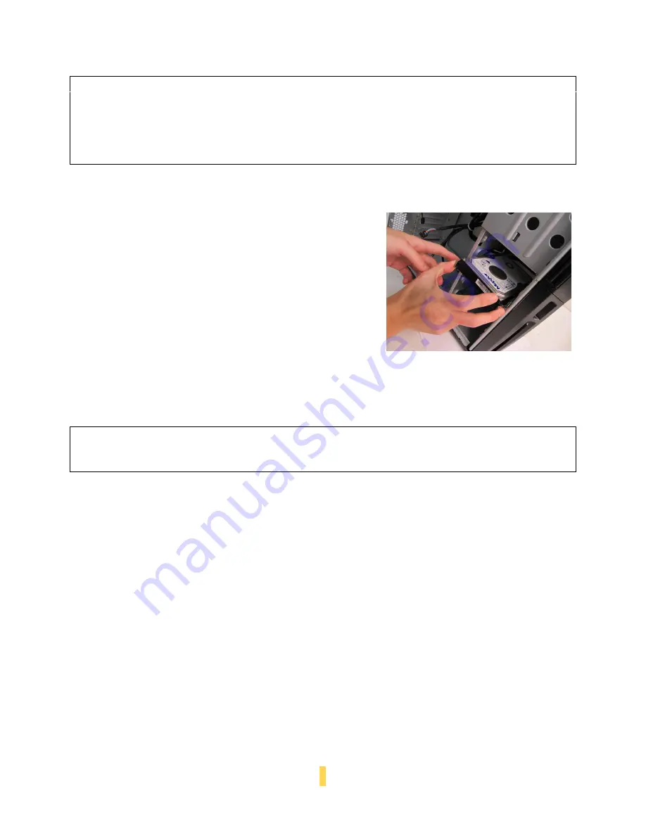
The Sonata Proto provides space for up to four internal 3.5” 
hard drives. Before you begin, remove the side panel as 
described in section 2.1.  

 
1.


With your thumb and forefinger, grasp the pinch tabs on 
either side of one of the internal 3.5” drive trays, and slide 
the drive tray outwards. 

2.


Mount your hard drive onto the internal 3.5” drive tray 
with the hard drive’s sockets facing towards the back of 
the tray.  

3.


Align and fasten the screw holes at the bottom of 
the hard drive with the holes in the included 
silicone grommets, using the included internal 3.5” 
drive tray screws. 


4.


Grasping the pinch tabs on either side of the 
internal 3.5” drive tray, partially insert the drive tray 
containing your 3.5” hard drive into the case. 

5.


Attach the Molex power leads from the PSU and the 
hard drive cable from your motherboard to the back 
of the hard drive. 

6.


Push the 3.5” drive tray containing your hard drive 
into the case all the way until clicks and locks into 
place. 


Note:    

The Sonata Proto comes with a CPU cutout on the motherboard tray, which will allow  


you to mount oversize CPU heatsinks, and also change your CPU heatsink without  


removing the motherboard. 


Note:    

The motherboard tray has standoffs pre-installed for the most common ATX mounting  


locations. Extra standoffs and screws are included.  

Caution:  

Do not torque or over-tighten the 3.5” internal drive tray screws.

 Compressing the  


silicone grommets will reduce their lifespan and will lessen or negate their vibration- 


insulating effect. Tighten the screws until you feel resistance, then STOP. 

Содержание Sonata Proto

Страница 1: ...SONATA PROTO USER S MANUAL...

Страница 2: ...nagement 11 2 3 Motherboard Installation 11 2 4 Internal 3 5 Drive Bay Device Installation 12 2 5 External 3 5 Drive Bay Device Installation 13 2 6 External 5 25 Drive Bay Device Installation 13 SECTI...

Страница 3: ...e cooling potential over the original Sonata and provide cooling airflow to front hard drives At Antec we continually refine and improve our products to ensure the highest quality It s possible that y...

Страница 4: ...P 3 SECTION 1 INTRODUCTION...

Страница 5: ...with the standard mounting holes in Mini ATX MicroATX and ATX motherboards only 5 Cable routing compartment This area is provided for you to tuck away unneeded connectors and cables 6 Power supply mo...

Страница 6: ...P 5 9 2 1 7 3 5 6 8 10 4 2 1 7 3 5 6 10 4...

Страница 7: ...l 3 5 drive bays Expansion Slots 7 Motherboard Size Mini ITX microATX Standard ATX Front I O Panel 2 x USB 2 0 External eSATA AC 97 HD Audio In and Out 1 3 PARTS INCLUDED In addition to the accessorie...

Страница 8: ...t grounding strap Before you connect a cable ensure that both connectors are correctly aligned and oriented Bent pins can be difficult to fix and may require replacement of the entire connector This m...

Страница 9: ...nd one side mounted front air intakes For optimum performance we recommend leaving the front air intake unobstructed The Sonata Proto can operate resting sideways as well as vertically Do not rest the...

Страница 10: ...P 9 SECTION 2 HARDWARE INSTALLATION...

Страница 11: ...e case Then grip the side panel with the latch and lift it away from the case until it detaches Caution The front panel is not removable Please do not attempt to remove or pry open the front panel Cau...

Страница 12: ...n side facing up The drive cages should be visible on the right side of the case with the power supply in the upper left 2 Make sure you have the correct I O panel for your motherboard If the panel pr...

Страница 13: ...ray partially insert the drive tray containing your 3 5 hard drive into the case 5 Attach the Molex power leads from the PSU and the hard drive cable from your motherboard to the back of the hard driv...

Страница 14: ...vided with the drive tray securely fasten your 3 5 device to the tray 4 Place the 3 5 external drive tray assembly containing your 3 5 device into the front panel and push until it clicks 5 Attach pow...

Страница 15: ...P 14 SECTION 3 CONNECTING THE FRONT I O PORTS...

Страница 16: ...the case 10 6 4 2 9 7 5 3 1 You can connect either the AC 97 or the HDA connector depending on your motherboard Locate the internal audio connectors from your motherboard or sound card and connect th...

Страница 17: ...ork gets disturbed 1 Determine which wires you need to remove in order to rewire your plug to match the USB pin outs on your motherboard refer to your motherboard user s manual Working on one connecto...

Страница 18: ...P 17 SECTION 4 COOLING SYSTEM...

Страница 19: ...A 1 1 m min 39 CFM 0 9mm H2O 0 04 inch H2O 25 dBA 1 6 W 4 2 OPTIONAL FANS There is one optional fan mounting location intake fans at the back of the HDD cage We recommend using Antec 120mm speed contr...

Страница 20: ...our 120mm fan to the four screw holes using the fan screws provided with the case 4 3 WASHABLE AIR FILTERS Your case features a washable removable front panel air filter To remove the air filter 1 Res...

Страница 21: ...P 20 SECTION 5 FREQUENTLY ASKED QUESTIONS...

Страница 22: ...o obtain another set Charges may apply Can I open the front door all the way to the left side panel No Damage to the hinge or front door may result The power supply will not run my ATI Nvidia other ma...

Страница 23: ...ard All our cases are designed to Intel specifications and are backwards compatible with older case standards so yes My power supply fan is not running Please contact 1 800 222 6832 for RMA service Wh...

Страница 24: ...tel 31 0 10 462 2060 fax 31 0 10 437 1752 Customer Support US Canada 1 800 22ANTEC customersupport antec com Europe 31 0 10 462 2060 europe techsupport antec com www antec com Copyright 2009 Antec In...

Отзывы: