background image

2

The Triple Chamber structure

Upon opening the top panel, you will find the case is divided into three separate 
chambers – the power supply chamber, the motherboard chamber and the HDD 
chamber.  This triple chamber structure isolates heat and noise from each section
resulting in much quieter and cooler operation than a traditional desktop case.

Installing the Motherboard

This manual does not cover CPU, RAM, or expansion card installation. Please con-
sult the motherboard manual for specific mounting instructions and troubleshoot-
ing.

The motherboard is located inside the main chamber with two 120 mm TriCool™ 
fans preinstalled right next to the CPU.

1. Lay the case down, with the open side facing up. The drive cages and power 

supply should be visible.

2. Make sure you have the correct I/O panel for the motherboard. If the panel 

provided with the case isn’t suitable, please contact the motherboard manufac-
turer for the correct I/O panel.

3. Line up the motherboard with the standoff holes, and remember which holes 

are lined up. Not all motherboards will match with all the provided holes; this is 
normal, and won’t affect functionally.

4.  Remove the motherboard by lifting it up.
5. Screw the brass standoffs into the threaded holes that line up with the mother-

board. Do not overtighten the standoffs. Some standoffs may be pre-installed 
for your convenience.

6.  Place the motherboard on the brass standoffs.
7. Attach the motherboard to the standoffs with the provided Philips-head 

screws. The motherboard is now installed.

Connecting the Power and LED

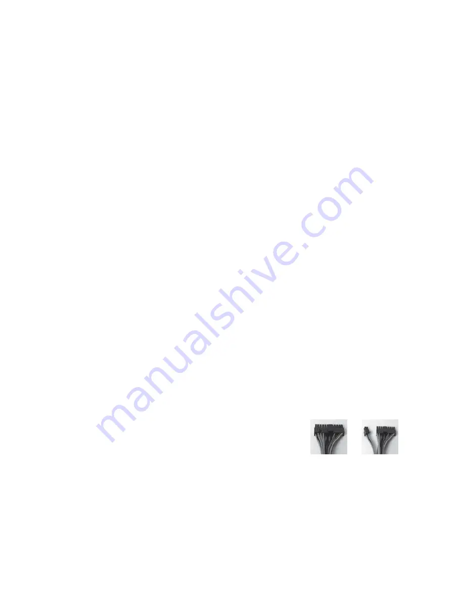
The power supply conforms to the ATX12V Version 2.01 standard. If the mother-
board has a 20-pin power receptacle, detach the 4-pin attachment on the 24-pin 
power connector, see pictures 1 and 2. Before you connect the power supply to 
any of the devices, please consult the appropriate user manuals for the mother-
board and other peripherals.

1. Connect the 24-pin Main Power Connector and the 4-

pin or 8-pin connector to the motherboard as needed. 
If the motherboard uses a 20-pin connector; detach 
the 4-pin attachment on the 24-pin power connector 
(see pictures 1 and 2). 

2. Connect the Reset switch (labeled RESET SW) to the 

motherboard at the RST connector. Make sure the 
label always faces the front of the case.

3. Power LED (labeled POWER LED) connector is located behind the Reset 

connector.

4. Power Switch (labeled POWER SW) connects to the PWR connector on the 

motherboard.

5.  Hard Drive LED (labeled H.D.D. LED) connects to the IDE connector.

Picture 1

Picture 2

For 24-pin

motherboards

For 20-pin

motherboards

Содержание NSK2400

Страница 1: ...New Solution Series NSK2400 ...

Страница 2: ...ince the power sup ply includes a soft on off feature This lets you turn the computer on and off by using the soft switch on the computer case If the computer crashes and you can t shut it down using the soft switch you can switch the main power to the OFF O position to clear the fault then reboot This power supply model features Power Factor Correction PFC circuitry in accor dance with European s...

Страница 3: ... up 5 Screw the brass standoffs into the threaded holes that line up with the mother board Do not overtighten the standoffs Some standoffs may be pre installed for your convenience 6 Place the motherboard on the brass standoffs 7 Attach the motherboard to the standoffs with the provided Philips head screws The motherboard is now installed Connecting the Power and LED The power supply conforms to t...

Страница 4: ...e front panel speaker and microphone connection If the motherboard supports Intel s standard onboard audio connector you can plug in the 10 pin connector directly onto the board For non Intel standard audio connec tion you need to plug the 7 individual connectors to the motherboard See instruc tion below Locate the internal audio connectors from the motherboard or sound card Consult the motherboar...

Страница 5: ...0 incorporates a rapid release Flip Up Drive Cage inside the power supply chamber for easy drive installation The cage can hold two 5 25 devices To install an external 5 25 device 1 Remove the flip up drive cage 2 Remove the drive bay cover you intend to install the device 3 Insert the 5 25 device into the cage Fasten the drive with the screws included See Picture 4 4 Find a 4 pin Molex or a SATA ...

Страница 6: ...edium or Low to a fan control device may result in the fan not being able to start The already lowered voltage from the fan control device will be further reduced by the TriCool circuitry below 5V Specifications Size 120mm x 120mm x 25 4mm Rated Voltage DC 12V Operating Voltage 10 2V 13 8V Speed Input Current Air Flow Static Pressure Acoustical Noise Input Power High 2000 RPM 0 24A Max 2 24 m min ...

Страница 7: ...l block the top air vents The Rear Air Intake There are vents right above the rear I O panel and on the PCI expansion slot cov ers to bring in fresh air to help cool the CPU and VGA card CPU Air Guide The CPU Air Guide and rear air intake work together to provide fresh air to the CPU cooler to enhance the CPU cooling The CPU Air Guide consists of several sections which can be adjusted to best suit...

Страница 8: ...ax 31 0 10 437 1752 Technical Support US Canada 1 800 22ANTEC customersupport antec com Europe 31 0 10 462 2060 europe techsupport antec com www antec com Copyright 2006 Antec Inc All rights reserved All trademarks are the property of their respective owners Reproduction in whole or in part without written permission is prohibited Printed in China Version 1 0 1 02 16 2006 ...

Отзывы: