Antaira Technologies - Industrial Ethernet Switches
LNP-0800G-M12-67-24 User Manual V1.0
9
Relay Contact
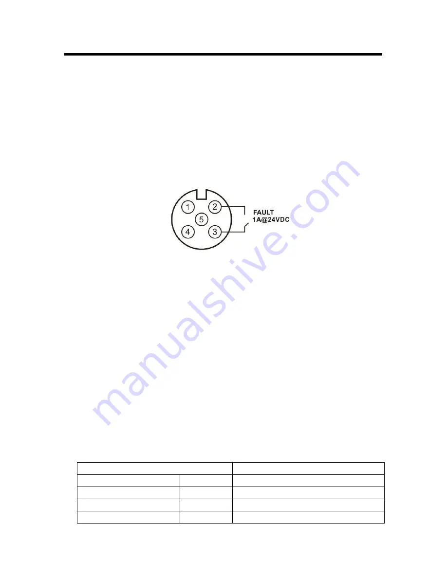
By using an M12 5-Pin A-Coded cable to connect the normally closed relay contact, it will detect
the fault status and form an open circuit when any of the following abnormal conditions occurs:
1. If the current PoE outputs of all connected PDs were overloaded (>200 Watts)
2. If the current PoE output of one or more PDs was overloaded (>30 Watts)
3. If Power 1 or Power 2 was inactive
A connection of relay contact for fault alarm is shown below in
Figure 2.5
.
Figure 2.5
When the Ethernet switch is operating normally, the relay contact is a closed circuit. When the
switch has any fault status (PoE overload or power failure), the relay contact circuit is opened and
the FAULT LED lights up. In addition, even after the abnormal situation has been removed, the
relay contact is still open and FAULT LED remains active, unless using the digital input to reset
that. See the next section for information on Digital Input.
Note:
If only using one power source, jumper Pin 1 to Pin 4 and Pin 2 to Pin 3 on the M12 4-Pin T-
Coded power cable to eliminate power fault alarm.
Digital Input (DI)
The digital input is used for monitoring two external events via an external voltage source. When
the voltage level on digital input pins changes from high voltage to low voltage, the DI function will
be triggered.
Table 2.9
shows a detail specification of the digital input.
Specification
Description
Level 0 (Low)
-30~8VDC
Will trigger DI function (active trigger states)
Level 1 (High)
10~30VDC
Normal Status (inactive trigger states)
Nominal Input Voltage
24VDC
Max. Input Voltage
30VDC


