


9
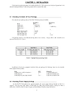
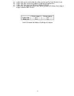
Tab.3-2 Power Supply Requirements
*A.C. power cannot be used
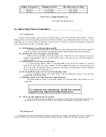
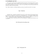
3.3 Determining Place of Installation
3.3.1 Scanner unit
A radar's target detection capacity varies greatly depending on the fitted position of the scanner. An ideal
fitting position is a location high above the ship's keel line where there is no obstacle all around the scanner. In an
actual ship, such an ideal location is limited by various factors. Therefore, consider the following suggestions
when you determine the place to install the scanner:
(a) Install scanner at a position as high as possible.
The higher the installation position, the longer the radio ranging distance. Install the scanner at
a position as high as possible after considering the ship's hull structure and radar maintainability.
(b) Install scanner away from smoke-stack and mast
If the scanner is installed at the same height as the smoke-stack or mast, radar waves may be
blocked, creating shadow zones or generating false echoes. Therefore, do not install the scanner at
such a position.
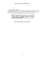
(c) Install scanner forward away from obstacle.
To avoid creating shadow zones or generating false echoes, install the scanner at a position
nearer to the ship's bow away from obstacles. When installing the scanner on a mast, position it in
front of the mast. (If obstacles cannot be avoided for the ship's structural reasons, refer to "Shifting
away from obstacles" described Page 13.)
(d) Do not install the scanner near hot or heat-generating items.
Do not install the scanner at a position where it may be subjected to smoke or hot air from
smokestacks or heat from lamps.
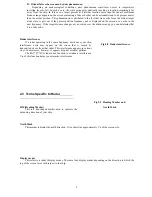
(e) Install the scanner away from antennas of other equipment.
Install the scanner as much away from the antennas of a direction finder, radio transceiver, etc.
as possible.
To eliminate the interference, install the scanner
away from the antenna of radio transceivers.
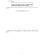
(f)
Make the cable length as short as possible.
Keep the distance from the scanner to the display unit within the standard cable length of 10 m.
If you use longer cable for unavoidable reasons, limit the cable length to a maximum of 100 m.
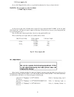
3.3.2 Display unit
The display unit can be installed on desktop, wall surface, or ceiling. Determine the place to install the
display unit that is convenient for navigation and radar operation after considering the following suggestions:
Supply voltage used
Maximum current
Allowable range of voltage
DC12V
3.5A or less
10.2-41.6V
DC24V
1.8A or less
10.2-41.6V
Содержание RA773UA
Страница 20: ...16 Fig 3 8 Fitting interconnecting cable seq Fig 22__Fitting_interconnecting_cable Arabic 1 ...
Страница 25: ...21 ...
Страница 28: ...24 4 4 Radar screen Dual screen ex PPI PPI screen 4 5 Radar screen All PPI screen ...
Страница 52: ...48 ...
Страница 84: ...80 Interconnecting cable 100 m max Noise D U 65 dB or less S U 65 dB or less RA773UA S U 75 dB or less RA774UA ...


