


6
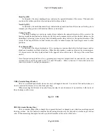
Head Up (HU)
In this mode, the ship's heading always indicates the upward direction of the screen. This mode lets
you know the relative positions of your ship and other ships or land.
North Up (NU)
In this mode, the north direction always indicates the upward direction of the screen, allowing you to
compare your ship position with a marine chart as you navigate.
Course Up (CU)
The ship's heading in a course-up mode always indicates the upward direction of the screen as the
bearing toward the destination. In this mode, the ship can be maneuvered to sail the shortest distance to the
destination by steering it in such a way that its heading marker always directs to the upward direction of the
screen. If the ship drifts due to tidal current, care must be taken because the fixed targets move to other
positions.
True Motion (TM)
In this mode, the ship is displayed as if it is moving on a marine chart while the fixed targets such as
islands and seashores are fixed in position. When the ship reaches a certain position on the screen (approx.
2/3 of screen size), the ship is placed back to the opposite side on the screen. (The top of the screen faces
north.)
Note: Navigation equipment such as a gyrocompass or magnet compass must be connected to your radar
system before it can be operated in NU, CU, and TM modes. (Refer to Section 3.9 for details on how to
connect your radar to navigation equipment.)
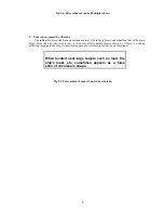
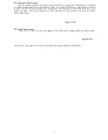
VRM (Variable Range Marker)
This is a circular-shaped marker whose size can be changed as desired. You can use this marker when you
want to examine the distance of an echo from your ship.
When measuring the distance of an echo from your ship, be sure to measure at a point close to the center of
the echo image on the screen.
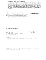
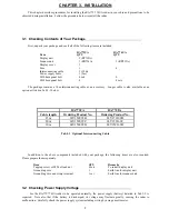
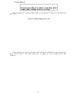
EBL (Electronic Bearing Line)
This is a marker shaped like a straight line segment that can be changed to any direction centering around
the ship position. Use this marker to examine the advancing direction of your ship and its relative angle with an
echo. When measuring the angle of an echo, position the marker at the center of the echo.
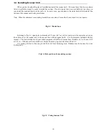
Fig.2-10 Display modes
Fig.2-11 VRM
Fig.2-12 EBL
Содержание RA773UA
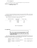
Страница 20: ...16 Fig 3 8 Fitting interconnecting cable seq Fig 22__Fitting_interconnecting_cable Arabic 1 ...
Страница 25: ...21 ...
Страница 28: ...24 4 4 Radar screen Dual screen ex PPI PPI screen 4 5 Radar screen All PPI screen ...
Страница 52: ...48 ...
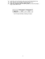
Страница 84: ...80 Interconnecting cable 100 m max Noise D U 65 dB or less S U 65 dB or less RA773UA S U 75 dB or less RA774UA ...


