background image

6-3 TD-LTE RF Measurements

TD-LTE Signal Analyzer

6-4

PN: 10580-00234  Rev. V

3GPP MG

RF Measurement Setups

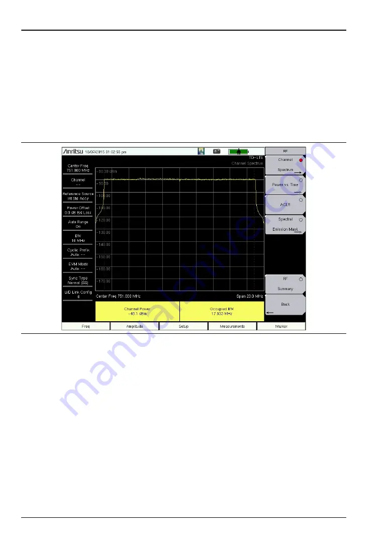
Channel Spectrum

1. 

Press the 

Measurements

 main menu key.

2. 

Press the 

RF

 submenu key.

3. 

Press the 

Channel Spectrum

 submenu key to activate this RF measurement view 

(

Figure 6-2

).

4. 

Press the 

Channel Spectrum

 submenu key again to select the Channel Spectrum menu, 

where you can adjust the span.

5. 

Press the 

Back

 submenu key to return to the RF menu.

Figure 6-2.

Channel Spectrum

Содержание BTS Master MT8221B

Страница 1: ...BTS Master User Guide MT8221B and MT8222B The High Performance Handheld Base Station Analyzer ...

Страница 2: ......

Страница 3: ...al documentation for the BTS Master features and options The documentation set is available as PDF files on the documentation disc and the Anritsu Web site Anritsu Company 490 Jarvis Drive Morgan Hill CA 95037 2809 USA http www anritsu com Part Number 10580 00207 Revision E Published March 2014 Copyright 2009 2014 Anritsu Company ...

Страница 4: ......

Страница 5: ... DAMAGES TO THE MAXIMUM EXTENT PERMITTED BY APPLICABLE LAW IN NO EVENT SHALL ANRITSU COMPANY OR ITS SUPPLIERS BE LIABLE FOR ANY SPECIAL INCIDENTAL INDIRECT OR CONSEQUENTIAL DAMAGES WHATSOEVER INCLUDING WITHOUT LIMITATION DAMAGES FOR LOSS OF BUSINESS PROFITS BUSINESS INTERRUPTION LOSS OF BUSINESS INFORMATION OR ANY OTHER PECUNIARY LOSS ARISING OUT OF THE USE OF OR INABILITY TO USE THE PRODUCT EVEN ...

Страница 6: ......

Страница 7: ...ralia and New Zealand Notes On Export Management This product and its manuals may require an Export License or approval by the government of the product country of origin for re export from your country Before you export this product or any of its manuals please contact Anritsu Company to confirm whether or not these items are export controlled When disposing of export controlled items the product...

Страница 8: ......

Страница 9: ...abels attached to products that are not shown in the diagrams in this manual This indicates a prohibited operation The prohibited operation is indicated symbolically in or near the barred circle This indicates a compulsory safety precaution The required operation is indicated symbolically in or near the circle This indicates a warning or caution The contents are indicated symbolically in or near t...

Страница 10: ...s equipment presenting a risk of severe injury or fatal electric shock to untrained personnel In addition there is a risk of damage to precision components Caution Electrostatic Discharge ESD can damage the highly sensitive circuits in the instrument ESD is most likely to occur as test devices are being connected to or disconnected from the instrument s front and rear panel ports and connectors Yo...

Страница 11: ...kplace 1 8 BTS Master Memory Types 1 8 Erase All User Files in Internal Memory 1 8 Recommended Usage in a Secure Environment 1 9 Chapter 2 Instrument Overview 2 1 Introduction 2 1 2 2 Hardware Overview 2 2 Turning On the MT8221B for the First Time 2 2 2 3 Front Panel Overview 2 3 2 4 Front Panel Keys 2 4 Main Menu Keys 2 5 Submenu Keys 2 5 2 5 Mode Selector Menu 2 6 2 6 Secondary Function Menus 2 ...

Страница 12: ...cy Bandwidth 3 2 3 4 Set the Amplitude 3 3 Setting Amplitude Reference Level and Scale 3 3 Setting Amplitude Range and Scale 3 3 Power Offset Set Up for Compensating External Loss 3 4 3 5 Set the Span 3 4 3 6 Setting Up Limit Lines 3 5 Single Limit Line 3 5 Segmented Limit Lines 3 5 Limit Line Envelope 3 6 3 7 Setting Up Markers 3 7 Selecting Activating and Placing a Marker 3 7 Selecting Activatin...

Страница 13: ...are 5 8 Using a USB Memory Device 5 8 Update Firmware Using Master Software Tools 5 10 Chapter 6 GPS Option 31 6 1 Introduction 6 1 6 2 Setting Up GPS Option 31 6 2 Activating the GPS feature 6 2 6 3 GPS Menu 6 4 Chapter 7 Anritsu Tool Box and Line Sweep Tools 7 1 Introduction 7 1 7 2 Anritsu Tool Box with Line Sweep Tools 7 1 7 3 Install the Software 7 1 7 4 Other Software 7 2 7 5 Why use Line Sw...

Страница 14: ...SB Device 8 5 Appendix A Measurement Guides A 1 Introduction A 1 Appendix B Error Messages B 1 Introduction B 1 B 2 Self Test or Application Self Test Error Messages B 1 B 3 Operation Error Messages B 2 Appendix C LAN and DHCP C 1 Introduction C 1 C 2 Ethernet Configuration C 1 LAN Connection C 1 Ethernet Config C 3 Ethernet Menu C 4 C 3 DHCP C 5 Example 1 C 6 Example 2 C 6 C 4 ipconfig Tool C 6 C...

Страница 15: ...he BTS Master MT8221B Additional instrument functions and descriptions of optional measurement capabilities are described in measurement guides Refer to Appendix A Measurement Guides for a list of these guides and their Anritsu part numbers 1 3 Contacting Anritsu To contact Anritsu please visit http www anritsu com contact asp From here you can select the latest sales select service and support co...

Страница 16: ...litude and bandwidth Dedicated keys for one button measurements of field strength channel power occupied bandwidth Adjacent Channel Power Ratio ACPR and Carrier to Interference Ratio C I make the handheld MT8221B the ideal choice for the field A familiar calculator type keypad allows for fast data entry In transmitter analyzer mode the MT8221B BTS Master displays 6 markers and the marker table in ...

Страница 17: ...t is dampened with water or with water and a mild cleaning solution Clean the RF connectors and center pins with a cotton swab dampened with denatured alcohol Visually inspect the connectors The fingers of N f connectors and the pins of N m connectors should be unbroken and uniform in appearance If you are unsure whether the connectors are good gauge the connectors to confirm that their dimensions...

Страница 18: ...harge may damage the MT8221B input circuitry MT8221B operators must be aware of the potential for ESD damage and take all necessary precautions Operators should exercise practices outlined within industry standards such as JEDEC 625 EIA 625 MIL HDBK 263 and MIL STD 1686 which pertain to ESD and ESDS devices equipment and practices Because these apply to the MT8221B Anritsu Company recommends that ...

Страница 19: ...ile it is installed in the BTS Master by using either the AC DC Adapter or the 12 Volt DC adapter or separately in the optional Dual Battery Charger Refer to your Technical Data Sheet for Anritsu part numbers Refer to section Symbols and Indicators on page 2 19 for a description of battery symbols Figure 1 1 Battery Compartment Door Note Use only Anritsu approved batteries adapters and chargers wi...

Страница 20: ...erting the BTS Master 2 Place the soft carrying case face down on a stable surface with the front panel fully closed and laying flat 3 Fully open the zippered back of the case 4 Insert the instrument face down into the case taking care that the connectors are properly situated in the case top opening You may find it easier to insert the connectors first then pull the corners over the bottom of the...

Страница 21: ...t bail provides a backward tilt for improved stability and air flow To deploy the tilt bail pull the bottom of the tilt bail away from the back of the instrument To store the tilt bail push the bottom of the bail towards the back of the instrument and snap the bail into the clip on the back of the instrument Figure 1 3 Tilt Bail Housed Figure 1 4 Tilt Bail Extended ...

Страница 22: ...set to standard factory default values RAM Memory This is volatile memory used to store parameters needed for the normal operation of the instrument along with current measurements This memory is reset whenever the instrument is restarted External USB Flash Drive This memory may be selected as the destination for saved measurements and setups for the instrument The user can also copy the contents ...

Страница 23: ...ash drive 1 Attach the external Flash drive and turn the instrument on 2 Press the Shift button then the File 7 button 3 Press the Directory Management submenu key 4 Confirm that USB is underlined in the Current Location key The external USB drive is now the default location for saving files Note For USB storage not all after market USB drives are compatible with the instrument Many drives come wi...

Страница 24: ...1 12 Secure Environment Workplace General Information 1 10 PN 10580 00207 Rev E BTS Master UG ...

Страница 25: ...pter 3 Basic Measurement Setups to find directions for power on editing frequency bandwidth amplitude limit line marker file management procedures and firmware update For more detailed information on measurement setups refer to the specific measurement guides which are based on the options that can be purchased for this instrument The measurement guides and a copy of this user guide are available ...

Страница 26: ...DC Adapter or 12 VDC Automotive Cigarette Lighter Adapter Both items are included as standard accessories To turn on the MT8221B press the On Off button on the front panel Figure 2 1 The MT8221B BTS Master takes approximately sixty seconds to complete power up and to load the application software At the completion of this process the instrument is ready to be used Caution When using the Automotive...

Страница 27: ... shift key to access the functions that are printed on the panel The Escape key which is used for aborting data entry is the round button located above the submenu keys The rotary knob the four arrow keys and the keypad can be used to change the value of an active parameter The rotary knob can also be pressed to duplicate the action of the Enter key Arranged in a vertical column on the instrument ...

Страница 28: ... below the measurement display screen the 5 main menu keys The hard keys perform as follows Esc Key Press this key to cancel any setting that is currently being made Enter Key Press this key to finalize data input Pressing the rotary knob performs this same function Arrow Keys The four arrow keys between the rotary knob and the Esc key are used to scroll up down left or right The arrow keys can of...

Страница 29: ... arranged adjacent to the measurement display screen and along its lower edge These keys buttons have no printed labels They are positioned to accompany virtual key labels that are displayed in the measurement display area These main menu key labels change to match specific instrument Mode settings Each Mode has a specific set of main menu keys For details about the main menu keys refer to the sec...

Страница 30: ...n the Mode 9 key Use the directional arrow keys or the rotary knob to highlight the selection and press the Enter key to select The list of modes that appears in this menu will vary depending upon the options that are installed and activated in your instrument Figure 2 4 is an example of the Mode menu Your instrument may not show the same list Figure 2 4 Mode Selector Menu ...

Страница 31: ...Function Menus are active in various operation Modes If any one of these 9 menus is available in a specific instrument Mode of operation then it can be called from the number keypad It may also be available from a main menu key or a submenu key The Secondary Function Menus are Preset 1 Calibrate 2 Sweep 3 Measure 4 Trace 5 Limit 6 File 7 System 8 and Mode 9 Figure 2 5 Keypad and Secondary Function...

Страница 32: ...es that are displayed on your BTS Master Cable and Antenna Analyzer Mode Figure 2 6 illustrates some of the key information areas of the MT8221B display For more detailed key descriptions of the Cable and Antenna Analyzer mode refer to the Cable and Antenna Analyzer Measurement Guide Anritsu part number 10580 00230 available on the documentation disc Also refer to Appendix A Measurement Guides for...

Страница 33: ...view 2 7 Display Overview BTS Master UG PN 10580 00207 Rev E 2 9 Figure 2 7 Spectrum Analyzer Display Real Time Clock Display Area Battery Charge Indicator Submenu Key Labels Instrument Settings Summary Main Menu Keys ...

Страница 34: ...t are unique to the MT8221B WCMDA HSDPA Signal Analyzer CDP display For WCDMA HSDPA information refer to the 3GPP Measurement Guide available on the documentation disc and the Anritsu web site Figure 2 8 WCDMA HSDPA Signal Analyzer CDP Display Overview Full View Zoom View Numerical Measurement Results Constellation View Control Channels ...

Страница 35: ...nnas or couplers can be added to list boxes by creating them and importing them through the use of Master Software Tools 2 9 Text Entry When entering text as when saving a measurement the submenu key for Text Entry displays the characters alphabet hyphen and underscore in 6 letters per key Refer to Figure 2 11 Characters can be entered by using the rotary knob or by using the submenu keys Refer to...

Страница 36: ...2 9 Text Entry Instrument Overview 2 12 PN 10580 00207 Rev E BTS Master UG Figure 2 9 Text Entry Menu Lower Case Figure 2 10 Text Entry Menu Upper Case Lowercase Text Entry Uppercase Text Entry ...

Страница 37: ...Instrument Overview 2 9 Text Entry BTS Master UG PN 10580 00207 Rev E 2 13 Figure 2 11 Text Entry Menu Selecting Characters Rotary Knob has scrolled to letter c ...

Страница 38: ...y into the contact fingers of the female connector 2 Push connectors straight together Do not twist or screw them together 3 To tighten turn the connector nut not the connector body Major damage can occur to the center conductor and to the outer conductor if the connector body is twisted 4 If you use a torque wrench then initially tighten by hand so that approximately 1 8 turn or 45 degrees of rot...

Страница 39: ... panel connectors are shown in Figure 2 12 and Figure 2 13 and are described in the following text Figure 2 12 Test Panel Connectors including E1 Ext Trigger In SPA RF In VNA Port 2 Ext RF In 10 MHz Ref Out RF Output IF Out Headset Jack USB Mini B A Type USB LAN External Power GPS Antenna E1 RJ48C Jack E1 Receive Transmit ...

Страница 40: ...amber LED shows the presence of a 10 Mbit s LAN connection when on and a 100 Mbit s LAN connection when off The green LED flashes to show that LAN traffic is present For additional information about the LAN connection Ethernet connection and DHCP refer to Appendix C Ethernet Configuration Figure 2 13 Test Panel Connectors Including T1 and T3 Warning When using the AC DC Adapter always use a three ...

Страница 41: ...rigger female BNC input connector causes a single sweep to occur In the Spectrum Analyzer mode it is used in zero span and triggering occurs on the rising edge of the signal After the sweep is complete the resultant trace is displayed until the next trigger signal arrives This port is also used for External Clock Recovery in T1 T3 E1 operations described in the Backhaul Measurement Guide Refer to ...

Страница 42: ...n wrench to tighten the Type N connector Do not overtighten the connector The recommended torque is 12 lbf in to 15 lbf in 1 36 N m to 1 70 N m E1 Rx Tx Connectors Female BNC connectors for transmit and receive To prevent damage to your instrument do not use pliers or a wrench to tighten the BNC connector Do not overtighten the connector T1 T3 Rx Tx Connector BERT tester Option 51 and Option 53 Ba...

Страница 43: ...size and color with the charge level Green with Black Plug body Battery is fully charged and external power is applied Green Battery is 30 to 100 charged Yellow Battery is 10 to 30 charged Red Battery 0 to 10 charged Lightning Bolt Battery is being charged any color symbol When the battery is charging either from the AC DC Adapter or the 12 Volt DC adapter the symbol changes to that shown in Figur...

Страница 44: ...nction specific menus in the active menu submenu labels These Main Menu keys vary in function based on the selected mode of operation Shift Mode 9 Refer to Mode Selector Menu on page 2 6 for more information on changing the instrument mode Table 2 1 lists the Main Menu Key labels for each mode of instrument operation Figure 2 16 Battery Not Installed Table 2 1 Mode Dependent Main Menu Keys Located...

Страница 45: ... menu selection The current submenu title is shown at the top of the active function block submenu key labels Refer to Figure 2 2 on page 2 3 Fixed WiMAX Freq Amplitude Setup Measurements Mobile WiMAX Freq Amplitude Setup Measurements Marker T1 FT1 E1 T3 T1 FT1 Configuration Pattern Loop Error Alarm Measurements Start Stop Table 2 1 Mode Dependent Main Menu Keys Located Below Measurement display M...

Страница 46: ...2 13 Firmware Overview Instrument Overview 2 22 PN 10580 00207 Rev E BTS Master UG ...

Страница 47: ...uides and their Anritsu part numbers 3 2 Measurement Setup Connect the Input Source Connect the input signal or antenna to the appropriate test connector on the top of the instrument For connector descriptions refer to Figure 2 12 on page 2 15 Editing and Entering Values Parameter values that are ready for editing are displayed in red on the submenu key After changing the value press Enter to set ...

Страница 48: ...e appropriate unit key Pressing the Enter key has the same affect as pressing the MHz submenu key The current setting is shown at the top of the instrument settings summary column on the left side of the measurement display Selecting Signal Standard 1 Press the Freq main menu key 2 Press the Signal Standard submenu key The Signal Standards dialog opens 3 Highlight a signal standard and press Enter...

Страница 49: ...nter key to set The y axis scale is automatically renumbered Note To change the current measurement units press the Units submenu key and select the required units from the submenu keys that are presented Press the Back submenu key to return to the Amplitude menu Note The Scale parameter cannot be changed when linear units are selected Watts or Volts Press the Amplitude submenu key and select Auto...

Страница 50: ... 0 dB When using the Up Down arrow keys the value changes in increments of 10 0 dB When using the keypad enter the new value then press Enter or the dB submenu key to set the value The power offset is displayed in the instrument settings summary column on the left side of the measurement display 3 5 Set the Span Spectrum Analyzer Interference Analysis and Power Meter Modes 1 Press the Span main me...

Страница 51: ...ed The limit line is displayed on the graph 3 Press the Single Limit submenu key to change the location of the limit line on the y axis 4 If necessary press the Set Default Limit submenu key to display the limit line Segmented Limit Lines Spectrum Analyzer and Interference Analysis Modes Initial Setup 1 Press the Limit Upper Lower submenu key to select the desired limit line Upper or Lower 2 Activ...

Страница 52: ...ng the Next Point Left submenu key 5 Press the Add Point submenu key to place a new point on the limit line Use the Point Freq and Point Value submenu keys to set the frequency and dB level of the point 6 Repeat step 5 until the desired number of points have been added Limit Line Envelope Spectrum Analyzer and Interference Analysis Modes 1 Complete step 1 through step 4 in the procedure for Settin...

Страница 53: ... to be moved 3 Use the rotary knob to place the marker on the desired frequency 4 Repeat Step 1 and Step 2 to activate and move multiple markers Selecting Activating and Placing a Delta Marker 1 Press the Marker 1 2 3 4 5 6 submenu key so that the desired delta marker number is underlined 2 Press the Delta On Off submenu key so that On is underlined The selected marker is displayed in red ready to...

Страница 54: ...3 8 PN 10580 00207 Rev E BTS Master UG ...

Страница 55: ...kly save measurements with a specific file name The BTS Master saves the measurement with the latest file name that was used to save a measurement and with a number that is automatically incremented and appended to the end of the file name For instance if the last measurement was saved with the name Site 1 Trace Save Measurement As saves the next measurement as Site 1 Trace_ 1 Site 1 Trace_ 2 etc ...

Страница 56: ... the file type you want to view Recall a Measurement From the File menu press the Recall Measurement submenu key select the measurement with the rotary knob or the Up Down arrow keys and press Enter Recall a Setup Press the Recall submenu key Confirm that the file type is Setup or All using the File Type key Select the setup file stp with the rotary knob or the Up Down arrow keys and press Enter R...

Страница 57: ...the File main menu press the Copy submenu key The Copy submenu and Copy dialog box are displayed 3 Select the file s to copy To select multiple files highlight the first then press the Select or De Select key to keep the file selected The file will be outlined in blue Repeat with all the files to copy To display files in a folder select the folder and press the Enter key 4 Press the Scroll key and...

Страница 58: ...Down arrow keys Press the Select or De Select key The file will be highlighted in blue when selected Press the Delete key and Enter to delete the selected file Delete Dialog Box Press the Delete submenu key to open the Delete dialog box Figure 4 3 The submenus allow sorting by file type name and saved date See the Delete Menu on page 4 12 for additional information Figure 4 3 Delete Dialog Box ...

Страница 59: ...ectories Recall Sort By Name Date Type Sort Order Asc Desc File Type ALL Select or De Select Delete Refresh Directories Delete Sort By Name Date Type Sort Order Asc Desc Scroll Scr Dst File Type ALL Refresh Directories Select or De Select Copy Copy Clear All Save On Crossing Limit On Off Sweep Complete On Off Save Then Stop On Off B A B A Sort By Name Date Type Sort Order Asc Desc Create Folder Se...

Страница 60: ...ve for external data storage Refer to the BTS Master Technical Data Sheet listed in Appendix A for the Anritsu Part Number of the USB flash drive The saved setup measurement or JPEG file can be named by using the text entry keys By default measurements are saved in a directory named user to internal memory The save destination is set with the Save Location Menu on page 4 8 Save on Event Spectrum A...

Страница 61: ... for capital letters Press the Enter key or the rotary knob to finalize a text entry Back Space Use this key to delete a file name highlighted in blue or delete individual characters Change Save Location Press this submenu key to open the Save Location Menu Change Type Press this submenu key to select what type of file is saved The options are the Measurement Setup or Jpeg The file type can be cha...

Страница 62: ... By Press this submenu key to sort the folders by Name Type or Date Sort Order Displays the folder names in ascending or descending order Create Folder This key will create a new folder in the highlighted location or folder The create directory dialog box will display for naming the folder Set Location This key will set the current location for saving files and return to the Save Menu on page 4 7 ...

Страница 63: ...oggling this submenu key to On will save the measurement to internal memory after the current sweep is complete If Save Then Stop is toggled Off a measurement will be saved after every sweep Save Then Stop Set this key to On to stop the sweep after a measurement is saved With this key Off and Sweep Complete On a measurement is saved after every sweep Clear All Pressing this key will turn Off the t...

Страница 64: ...he Sort By key File Type Press this submenu key to select what type of file is viewed The options are the ALL Measurement or Setup The file type can be changed with the Up Down keys or the rotary knob Press Enter to make the selection Setup Setup files contain basic instrument information measurement mode setup details measurement marker data and limit data Measurement Measurement files contain al...

Страница 65: ...Measurement Setup or Jpeg The file type can be changed with the Up Down keys or the rotary knob Press Enter to make the selection Refresh Directories Press this key to update the display Scroll Press this submenu key to use the scroll function in the Source Folder Scr top panel or Destination Folder Dst bottom panel See Figure 4 2 Note Previously saved files are not visible in this window Select o...

Страница 66: ...Type Press this submenu key to select what type of file view for deleting The options are the ALL Measurement Setup Limit Lines or Jpeg The file type can be changed with the Up Down keys or the rotary knob Press Enter to make the selection Select or De Select Use this key to select or deselect the file s or folder s to be deleted When selected a file or folder will be outlined in blue Delete Press...

Страница 67: ...chapter will review the BTS Master system operations System Menu Overview on page 5 2 System Menu on page 5 3 Preset Menu on page 5 7 Self Test on page 5 7 Update Firmware on page 5 8 The other menus Sweep Measure Trace and Limit are detailed in the Measurement Guides listed in Appendix A ...

Страница 68: ...on the instrument only under special circumstances refer to menu descriptions Figure 5 1 System Menus GPS System Back System Options Application Options GPS GPS On Off GPS Voltage 3 3 V 5 V Status Self Test Application Self Test GPS Info Reset Calibrate Touch Screen Back Reset Factory Defaults Master Reset Update Firmware Set Remote Access Password Share CF Pwr Offset All Modes Not Shared System O...

Страница 69: ...nce of the instrument hardware and that are specific to the current instrument application refer to Mode Selector Menu on page 2 6 Press the Esc key to abort or press the Enter key to continue The display lists a summary of those tests that have passed If any test fails then all of the performed tests are listed with Pass Fail notification If any test fails then contact your Anritsu Service Center...

Страница 70: ...nslations available English is the default language Press Enter to accept the change or press the Esc key to return to normal operation without changes In addition any existing language except English may be edited for a better local translation Note A SYSTEM ON Factory Default reset will overwrite any custom settings within the BTS Master and will require that you reload the custom language files...

Страница 71: ...o All Modes or to Not Shared Select All Modes to have the current center fre quency setting and power offset setting carried over when changing measure ment modes This function is not applicable to measurements that do not have a center frequency or power offset setting or to measurements in which the current center frequency or power offset setting is outside the range of the new measurement Set ...

Страница 72: ...eters including Ethernet language and brightness settings Also all user files in the internal memory are deleted and the original language and antenna files are restored Press the Enter key to initiate the reset The BTS Master is automatically rebooted as part of this operation To return to normal operation without resetting press Esc rather than pressing Enter Note This same reset sequence can be...

Страница 73: ...act your Anritsu Service Center To initiate a self test when the system is already powered up 1 Press the Shift key and then the System 8 key 2 Press the Self Test submenu key The Self Test results are displayed Press the Esc key to continue Preset This key resets the instrument to the default starting conditions Save Setup Opens the Save dialog box to name and save the current operating settings ...

Страница 74: ...rocess After the firmware is loaded onto the USB memory device follow the instructions below to update the firmware on your BTS Master 1 Insert the USB Memory Stick into the USB port 2 Press the follow key sequence Shift System 8 System Options Reset Update Firmware The Load Firmware main menu key is displayed Figure 5 8 3 Press the Load Firmware main menu key to list the Firmware Update menu and ...

Страница 75: ...ice Save Restore User data will be saved to the selected external media device The instrument will also attempt to restore the files to the instrument after the update 6 Press Enter to begin the firmware update process To abort the process press Esc then choose another analyzer mode or power down Figure 5 9 Firmware Update Menu Warning If there is not enough available memory space for all user dat...

Страница 76: ...igure 5 10 8 Select Enter and the firmware update process begins and the Firmware Update dialog displays the following message Updating firmware Please Wait 9 When complete the instrument will reboot Update Firmware Using Master Software Tools Refer to Updating Instrument Firmware on page 8 2 in Chapter 5 System Operation Figure 5 10 Firmware Update Menu ...

Страница 77: ...r 3 Basic Measurement Setups to find directions for power on editing frequency bandwidth amplitude limit line marker file management procedures and firmware update For more detailed information on measurement setups refer to the specific measurement guides which are based on the options that can be purchased for this instrument The measurement guides and a copy of this user guide are available as ...

Страница 78: ...u 3 Press the GPS submenu key to display the GPS menu refer to GPS Menu on page 6 4 4 Activate GPS by pressing the GPS On Off submenu key so that On is underlined When GPS is first turned On the GPS icon is displayed in red 5 Press the GPS Info submenu key to open the GPS Info window which displays a Tracked Satellites b Latitude c Longitude d Altitude e UTC timing information f Fix available g An...

Страница 79: ...nternal standard accuracy is 0 3 PPM The correction factor applied to the internal OCXO allows the instrument to maintain GPS frequency accuracy for three days at better than 50 ppb even when the instrument is obstructed from receiving signals from the GPS satellites In order to acquire data from the GPS satellites you must have line of sight to the satellites or the antenna must be placed outside...

Страница 80: ...e to be either 3 3 V or 5 V depending on the GPS receiver being used GPS antenna voltage is set to 3 3 V by default in order to prevent accidental damage to lower voltage GPS antennas Note Typical base station GPS antennas are 5V please check your antenna voltage to choose the correct value Reset Press this submenu key to reset the GPS for a new location Back Press this submenu key to return to th...

Страница 81: ...sit the Anritsu web site or launch an Anritsu application To open the Anritsu Tool Box either click on the shortcut icon on the desktop or click Start and navigate through the Programs folder to the Anritsu folder Then click on the Anritsu Tool Box shortcut to open the Anritsu Tool Box Once the Tool Box is open move the mouse pointer over any of the application icons to view a short description of...

Страница 82: ...e Intermodulation PIM traces every day Line Sweep Tools will Collect sweeps from Anritsu PIM and Line Sweep gear Help verify that those sweeps are done properly and that the Cable Antenna and PIM sweeps meet specifications Help create reports of the findings quickly and to a professional standard Line Sweep Tools Features The Line Sweep Tools user interface is familiar to users of Handheld Softwar...

Страница 83: ...easurements 7 6 Using Line Sweep Tools Line Sweep Tools is intuitive for most users It has the capability to work rapidly with a large number of traces Line Sweep Tools can open DAT files from HHST or VNA DAT files from Anritsu s E series instruments It also can open PIM files Either way the file once opened can be inspected and modified in many different ways Line Sweep Tools saves files as a new...

Страница 84: ...e preset toolbar allows users to quickly set all markers and the limit line to pre defined values on similar traces Figure 7 5 First set the markers and limit lines on a typical trace to the desired values Then press the red e or edit button on the Preset toolbar This puts the preset buttons into learn mode Now press a preset button 1 to 7 This programs the preset button where to put the markers a...

Страница 85: ...he renaming process simpler To use the renaming grid 1 Click on the left icon of the Renaming toolbar 2 Select the filename title or subtitle box Right clicking on a box will allow you to change the text on the button 3 Press buttons and type until the desired name is shown 4 Press Remember Fields to copy the new name for later use 5 On the toolbar press the button that corresponds to the field to...

Страница 86: ... the report generator in Line Sweep Tools go to File menu and select Report Setup to tell Line Sweep Tools how you want the report to appear In this case the report will have the name of the contractor that did the work Company field the contractor logo and will be generated in PDF format Figure 7 7 Figure 7 7 Report Setup Tab ...

Страница 87: ...ine Sweep Tools BTS Master UG PN 10580 00207 Rev E 7 7 Once the report generator is setup File Generate Report will create the PDF The report will include all traces that were open at the time the report was made Figure 7 8 Figure 7 8 Generated Report ...

Страница 88: ...7 8 PN 10580 00207 Rev E BTS Master UG ...

Страница 89: ...reen and associated data from the test instrument to the Master Software Tools Graphic Display Editor window Saved files on the test instrument can also be retrieved and displayed or edited with Master Software Tools Editing Graphs MST can be used to change the scale limit lines and markers in a measurement through the Edit Graph button in the workspace toolbar or through the Context Menus Context...

Страница 90: ...ols MST User Guide on the CD ROM for information regarding connecting your BTS Master to a PC 2 Run Master Software Tools 3 FromtheConnectionmenu for a USB Connection Select Connect USB for an Ethernet Connection a Enter the IP Address of your BTS Master by first clicking Enter IP Address b Then click Connect Ethernet xxx xxx xxx xxx In either type of connection the connection type is displayed in...

Страница 91: ...immediately click Install to Unit to update your BTS Master with the new firmware File Status Available In Figure 8 4 the status of the highlighted file is Available and the Install to Unit button is gray and inactive This means that the updated file is on the Anritsu Product Support Web site and needs to be downloaded to your PC After the file has been downloaded and placed on your PC its status ...

Страница 92: ... Click the Install to Unit button Your BTS Master is updated with the new firmware File Status Available 1 Check that the file status is Available 2 Click Retrieve File to download the file from the Web site to your PC 3 Check that the file status changes to Ready 4 Click the Install to Unit button Your BTS Master is updated with the new firmware Figure 8 4 Product Updates Window Status Available ...

Страница 93: ...found are listed in the file menu 2 Click the Retrieve File button The file is transferred from the Web site to your PC 3 After the status changes to Ready click the now active Install to Unit button Your BTS Master is updated with the new firmware Update Problems If you do not find the latest update or if you encounter a problem with updating the firmware then contact Anritsu Internet links to wo...

Страница 94: ...8 5 Updating Instrument Firmware Master Software Tools 8 6 PN 10580 00207 Rev E BTS Master UG ...

Страница 95: ...Master Software Tools 8 5 Updating Instrument Firmware BTS Master UG PN 10580 00207 Rev E 8 7 ...

Страница 96: ...8 5 Updating Instrument Firmware Master Software Tools 8 8 PN 10580 00207 Rev E BTS Master UG ...

Страница 97: ...Master Software Tools 8 5 Updating Instrument Firmware BTS Master UG PN 10580 00207 Rev E 8 9 ...

Страница 98: ...8 5 Updating Instrument Firmware Master Software Tools 8 10 PN 10580 00207 Rev E BTS Master UG ...

Страница 99: ...ware V1 36 and BEFORE Spectrum Analyzer Measurement Guide 10580 00244 for Firmware AFTER V1 36 High Accuracy Power Meter 0019 Power Meter Measurement Guide 10580 00240 Vector Signal Generator 0023 Signal Generator Measurement Guide 10580 00232 GSM GPRS EDGE RF Signal Analyzer 0040 GSM GPRS EDGE Demodulated Signal Analyzer 0041 W CDMA HSDPA RF Signal Analyzer 0044 W CDMA Demodulated Signal Analyzer...

Страница 100: ...2 16 Mobile WiMAX RF Signal Analyzer 0066 IEEE 802 16 Mobile WiMAX Demodulated Signal Analyzer 0067 IEEE 802 16 Mobile WiMAX Over the Air Signal Analyzer 0037 WiMAX Signal Analyzer Measurement Guide 10580 00236 T1 Analyzer 0051 E1 Analyzer 0052 T3 T1 Analyzer 0053 BTS Master MT8221B 22B with Option 450 Comms Board T1 Analyzer 0055 E1 Analyzer 0054 OC 3C Signal Analyzer 0058 T3 T1 Analyzer 0059 Bac...

Страница 101: ...ill erase all user saved setups and measurement traces and return the unit to a fully Factory Default condition If the error persists contact your Anritsu Service Center Lock Test FAILED One or more Phase Lock Loops Failed to properly achieve Lock Status Insure that the battery level is adequate for operation or that temperature is within acceptable limits Reset to factory defaults with either Fac...

Страница 102: ...tenuation increasing the Reference Level should resolve the error See also the Mixer Overdrive error above for information on Out of band RF power Calibrator Reading Error Calibration reference source is not providing quality signal Insure that the battery level is adequate for operation or that temperature is within acceptable limits Reset to factory defaults with either Factory Defaults ESC ON o...

Страница 103: ...r Sideband Demodulation mode Trace A B C has no data to view Attempt to turn on or VIEW a trace that has never had data recalled into this trace location Refer to Recall Trace section for instructions on how to recall stored measurement traces into either Trace A B or C Locking to Internal Ref failed Switching from an external frequency reference to the internal reference has failed Some additiona...

Страница 104: ...rker Current Marker is not ON Attempted to use a marker mode or feature for a marker that is not enabled Turn on the appropriate marker to use this function or switch to a marker that is already enabled Marker must be ON to Use the feature Attempted to use a marker mode or feature for a marker that is not enabled Turn on the appropriate marker to use this function or switch to a marker that is alr...

Страница 105: ...on or that the temperature is within acceptable limits Reset to factory defaults with either Factory Defaults ESC ON or MASTER RESET System ON Caution Use of MASTER RESET System ON will erase all user saved setups and measurement traces and return the unit to a fully Factory Default condition If the error persists contact your Anritsu Service Center Cannot set Delta Mkr Freq to Demod Freq Marker t...

Страница 106: ...ructions and allowing the unit to cool reset to the factory defaults with either Factory Defaults ESC ON Caution Use of MASTER RESET System ON will erase all user saved setups and measurement traces and return the unit to a fully Factory Default condition If the error persists contact your Anritsu Service Center Copy failed Please check External USB Memory Attempt to copy user saved data to the ex...

Страница 107: ...ic Host Configuration Protocol DHCP is an Internet protocol that automates the process of setting IP addresses for devices that use TCP IP and is the most common method of configuring a device for network use To determine if a network is set up for DHCP connect the MT8221B to the network and select DHCP protocol in the Ethernet Config menu Turn the BTS Master off and then on If the network is set ...

Страница 108: ... the instrument on press the Shift key then the System 8 key then the System Options soft key and the Ethernet Config soft key The IP address will be displayed as shown in Figure C 1 The image on the display panel of your BTS Master may differ from the image shown here Figure C 1 IP Address Assigned Using DHCP ...

Страница 109: ... BTS Master UG PN 10580 00207 Rev E C 3 Ethernet Config Press this submenu key to display the Ethernet submenu and to open the Ethernet Editor dialog box in order to set the IP address of the instrument Figure C 2 Setting IP Address Manually ...

Страница 110: ...er to accept the changes or press the Esc key to return to normal operation without changing anything Field IP G Way Sub Press this submenu key to select the desired Internet Protocol Property to be edited First Octet Moves the cursor to the left most column of the selected IP properties field Second Octet Moves the cursor to the second column from the left of the selected IP properties field Thir...

Страница 111: ...r being set it will always remain the same and care must be taken to not conflict with other equipment on the network When using a static IP address on an established network always request the Static IP address from the network administrator Randomly choosing a Static IP address on an established network may result in duplicate IP addresses or other conflicts Three parameters must be set prior to...

Страница 112: ...Gateway 153 56 100 1 Subnet Mask 255 255 252 0 C 4 ipconfig Tool A few tools that are built into the Microsoft Windows operating system can assist in making some determinations about the network to which the PC is connected Typing ipconfig at a command prompt produces a display of information about the in use parameters of the PC and its network connection Following is an example of the typical re...

Страница 113: ...id connection is found then a copy of the signal that was sent is returned If a connection is not found then the response is request timed out which means that no reply was received from that IP address Y ping 172 26 202 172 Pinging 172 26 202 172 with 32 bytes of data Reply from 172 26 202 172 bytes 32 time 10ms TTL 128 Reply from 172 26 202 172 bytes 32 time 10ms TTL 128 Reply from 172 26 202 17...

Страница 114: ...C 8 PN 10580 00207 Rev E BTS Master UG ...

Страница 115: ...apter 1 5 2 2 approved batteries and chargers 2 19 cleaning solvents 1 3 ESD 1 4 center frequency sharing 5 5 change directory 4 7 connector care 2 14 connectors test panel illustration 2 15 contacting Anritsu 1 1 copy menu 4 11 create folder 4 8 D default gateway for IP address C 5 defaults factory B 1 demod frequency B 5 DHCP LAN connection C 1 more information C 5 documents reference 1 4 Dynami...

Страница 116: ...t guides A 1 measurements selecting signal standard 3 2 setting amplitude 3 3 setting bandwidth 3 2 setting frequency 3 2 setting span 3 4 setting up GPS 6 2 setting up limit lines 3 5 setting up markers 3 7 menu copy 4 11 delete 4 12 Ethernet C 4 file 4 6 GPS 6 4 mode selector 2 6 options system 5 4 preset 5 7 recall 4 10 reset 5 6 save 4 7 save location 4 8 save on event 4 9 system 5 3 system op...

Страница 117: ... system options 2 2 menu 5 5 T T1 T3 Bantam Jacks 2 18 test panel 2 15 tilt bail 1 7 trigger external 2 17 external connector 2 15 U updates product updates window 8 2 updating firmware via Ethernet 8 2 via USB 5 8 8 2 URL contacting Anritsu 1 1 USB error Beat Frequency Oscillator B 3 flash drive memory 1 3 interface to PC 2 17 Type A 2 17 Type Mini B 2 17 updating firmware 5 8 8 2 V VNA Reflectio...

Страница 118: ...Index 4 PN 10580 00207 Rev E BTS Master UG ...

Страница 119: ...Anritsu Company 490 Jarvis Drive Morgan Hill CA 95037 2809 P N 10000 00000 Revision Prelim Printed March 2014 ...

Страница 120: ...Anritsu Company 490 Jarvis Drive Morgan Hill CA 95037 2809 USA http www anritsu com Anritsu utilizes recycled paper and environmentally conscious inks and toner ...

Страница 121: ... 556 For some models RF Demod and OTA are combined as a single option GSM GPRS EDGE Option 880 W CDMA HSPA Option 881 TD SCDMA HSPA Option 882 LTE LTE A FDD and TDD Option 883 Note Not all instrument models offer every option or every measurement within a given option Please refer to the Technical Data Sheet of your instrument for available options and measurements within the options Anritsu Compa...

Страница 122: ...hall not be reproduced copied or used in whole or in part as the basis for manufacture or sale of the equipment or software programs without the prior written consent of Anritsu Company Updates Updates if any can be downloaded from the Anritsu Website at http www anritsu com For the latest service and sales contact information in your area please visit http www anritsu com contact us Product Infor...

Страница 123: ... GPRS EDGE Signal Analyzer 2 1 Introduction 2 1 2 2 Measurement Setup 2 2 2 3 GSM GPRS EDGE RF Measurements 2 2 2 4 Measurement Display 2 2 2 5 Demodulator 2 5 2 6 GSM GPRS EDGE Mode Pass Fail 2 7 Pass Fail Mode Procedure 2 7 2 7 Measurement Results 2 8 2 8 GSM GPRS EDGE Menus 2 10 2 9 Freq Frequency Menu 2 11 2 10 Amplitude Menu 2 12 2 11 Setup Menu 2 12 2 12 Measurements Menu 2 13 Spectrum Menu ...

Страница 124: ... 3 7 Channel Spectrum Setup 3 8 Channel Spectrum Procedure 3 8 ACLR Measurement Setup 3 9 ACLR Measurement Procedure 3 9 ACLR Multi channel ACLR Procedure 3 11 Spectral Emission Mask Setup 3 11 Spectral Emission Mask Procedure 3 12 RF Summary 3 13 3 5 Demodulator 3 14 Zoom Function 3 14 Code Domain Power CDP Setup 3 14 Code Domain Power CDP Procedure 3 15 HSPA Setup 3 17 HSPA Procedure 3 17 Codogr...

Страница 125: ...s Fail Mode Menu 3 41 ScriptMaster Menu 3 41 3 13 Marker Menu 3 42 3 14 Sweep Menu 3 42 3 15 Measure Menu 3 43 3 16 Trace Menu 3 43 3 17 Limit Menu 3 43 3 18 Other Menus 3 43 Chapter 4 TD SCDMA HSPA Signal Analyzer 4 1 Introduction 4 1 4 2 General Measurement Setups 4 1 4 3 TD SCDMA HSPA RF Measurements 4 1 Measurement Setup 4 2 Channel Spectrum 4 3 Power versus Time 4 4 RF Summary 4 6 4 4 TD SCDM...

Страница 126: ...lator Menu 4 24 Over The Air Menu 4 25 Pass Fail Mode Menu 4 26 4 12 Sweep Menu 4 27 4 13 Measure Menu 4 27 4 14 Trace Menu 4 27 4 15 Limit Menu 4 27 4 16 Other Menus 4 27 Chapter 5 LTE Signal Analyzer 5 1 Introduction 5 1 5 2 General Measurement Setups 5 1 Antenna Status 5 2 5 3 LTE RF Measurements 5 3 Channel Spectrum 5 3 ACLR 5 3 Spectral Emission Mask 5 3 RF Summary 5 3 RF Measurement Setups 5...

Страница 127: ...quency Menu 5 28 Standard List Menu 5 29 5 10 Amplitude Menu 5 30 5 11 Setup Menu 5 31 5 12 Measurements Menu 5 32 RF Menu 5 33 Modulation Menu 5 34 Power vs Resource Block Menu 5 35 Constellation Menu 5 36 Control Channel Power Menu 5 37 Over the Air Menu 5 38 OTA Scanner Menu 5 39 Over the Air Tx Test Menu 5 40 Coverage Mapping Menu 5 41 Carrier Aggregation Menu 5 42 Component Carrier Menu 5 43 ...

Страница 128: ...B 6 9 Constellation 6 10 Control Channel Power 6 11 Tx Time Alignment 6 11 Modulation Summary 6 11 Modulation Measurement Setups 6 12 6 5 TD LTE Over the Air OTA Measurements 6 17 Antenna Status 6 17 Scanner 6 17 Tx Test 6 18 Mapping Coverage Mapping 6 18 Carrier Aggregation 6 18 EMF Option 444 only 6 19 Measurement Setup 6 19 6 6 Pass Fail Tests 6 22 6 7 TD LTE Summary 6 23 Measurement Setup 6 24...

Страница 129: ...enu 6 44 Carrier Aggregation Menu 6 45 Component Carrier Menu 6 46 EMF Menu 6 46 Pass Fail Test Menu 6 47 6 13 Marker Menu 6 48 Power vs Resource Block Marker Menu 6 49 6 14 Calibrate Menu 6 49 6 15 Sweep Menu 6 49 6 16 Measure Menu 6 50 6 17 Trace Menu 6 50 6 18 Limit Menu 6 50 6 19 Other Menus 6 50 Chapter 7 LTE and TD LTE Coverage Mapping 7 1 Introduction 7 1 7 2 General Measurement Setups 7 1 ...

Страница 130: ...ntenna 8 1 8 3 LTE TD LTE EMF Menu 8 2 Meas Params Menu LTE TD LTE 8 3 RS Display Menu 8 4 P SS Display Menu 8 5 S SS Display Menu 8 6 Measurement Results LTE TD LTE 8 7 Pass Fail 8 9 8 4 W CDMA EMF Menu 8 10 Meas Params Menu W CDMA 8 12 Display Menu 8 13 Measurement Results W CDMA 8 14 Pass Fail 8 15 Appendix A Error Messages A 1 Introduction A 1 A 2 3GPP Messages A 1 Warning Messages A 1 Notific...

Страница 131: ...E Measurements requires Option 9 Option 40 GSM EDGE RF Measurements Option 41 GSM EDGE Demodulation W CDMA HSPA W CDMA HSPA signal analysis is described in Chapter 3 W CDMA HSPA Signal Analyzer Option 881 W CDMA HSPA Measurements requires Option 9 Option 44 W CDMA HSPA RF Measurements Option 45 W CDMA Demodulation Option 65 W CDMA HSPA Demodulation Option 35 W CDMA HSPA Over the Air OTA Measuremen...

Страница 132: ...E A Modulation Measurements Option 546 LTE LTE A OTA Measurements requires Options 31 542 and 543 15 and 20 MHz bandwidth for full functionality TD LTE TD LTE signal analysis is described in Chapter 6 TD LTE Signal Analyzer Option 883 LTE LTE A FDD TDD Measurements Option 551 TD LTE LTE A RF Measurements Option 552 TD LTE LTE A Modulation Measurements Option 556 TD LTE LTE A OTA Measurements requi...

Страница 133: ...easurement mode press Shift then the Mode 9 button to open the Mode Selector list box Highlight the desired measurement mode using the Up or Down arrow keys or the rotary knob and press Enter The list of available applications depends on the options that are installed and activated on your instrument Figure 1 1 Mode Selector List Box ...

Страница 134: ...support contact information for your country or region You can also provide online feedback complete a Talk to Anritsu form to have your questions answered or obtain other services offered by Anritsu Updated product information can be found on the Anritsu website http www anritsu com Search for the product model number The latest documentation is on the product page under the Library tab Figure 1 ...

Страница 135: ...strument can be directly connected to any GSM GPRS EDGE base station for accurate measurements When a physical connection is not available or required the instrument can receive and demodulate GSM GPRS EDGE signals over the air GSM GPRS EDGE RF measurements provide views of spectrum power versus time frame power versus time slot with mask and summary screens The spectrum view displays channel spec...

Страница 136: ...E submenu key and highlight Auto to select the GSM or EDGE signal 3 The instrument has automatic external reference frequency detection or if equipped activate GPS to get GPS High Accuracy frequency error measurements Refer to the User Guide for GPS setup information 2 4 Measurement Display Press the Measurements main menu key to select measurement display options To display Spectrum press the Spe...

Страница 137: ...GSM GPRS EDGE Signal Analyzer 2 4 Measurement Display 3GPP MG PN 10580 00234 Rev V 2 3 Figure 2 1 GSM Single Channel Measurement Figure 2 2 GSM Multi Channel Measurement ...

Страница 138: ...the Power versus Time Frame measurement Figure 2 3 To display Power versus Time Slot press the Power versus Time Slot submenu key to activate the Power versus Time Slot measurement Figure 2 4 The mask is according to the 3GPP TS 05 05 specification The first slot information is displayed Figure 2 3 GSM Power vs Time Frame Measurement Figure 2 4 GSM Power vs Time Slot Measurement ...

Страница 139: ...bmenu key and highlight Auto to automatically select the GSM or EDGE signal 4 The instrument has automatic external reference frequency detection or if equipped activate GPS to get GPS High Accuracy frequency error measurements Refer to the User Guide for GPS setup information 5 Press the Measurements main menu key 6 Press the Demodulator submenu key Note Highlight GSM or EDGE to set the instrumen...

Страница 140: ... GSM GPRS EDGE Signal Analyzer 2 6 PN 10580 00234 Rev V 3GPP MG To display the GSM EDGE Summary screen Figure 2 7 press the GSM EDGE Summary soft key Figure 2 6 EDGE Demodulator Measurement Figure 2 7 GSM EDGE Summary ...

Страница 141: ...ls a custom test set can also be created and downloaded to the instrument All measurement parameters can be selected for pass fail testing Pass Fail Mode Procedure 1 Set the frequency as described in the User Guide 2 Press the Measurements main menu key 3 Press the Pass Fail Mode submenu key to activate Pass Fail Mode 4 Press the Pass Fail Mode submenu key to display the Pass Fail Mode menu and th...

Страница 142: ...ime slots in a frame BSIC NCC BCC This is the Base Station Identity Code broadcasted on GSM systems The code consists of a Network Color Code NCC and a Base Station Color Code BCC Phase Err RMS deg The RMS phase error measured in degrees between the received signal and an ideal reconstructed reference signal of the first active slot Phase Err Pk deg The peak phase error measured in degrees between...

Страница 143: ...he undesired signal power interferer in dB This value is an estimate that is derived from the measured RMS EVM value This measurement is applicable to an EDGE signal only Modulation Type The modulation type can be GMSK for GSM signals or 8PSK for EDGE signals Mag Err rms The RMS of the magnitude error between the received signal and an ideal reconstructed reference signal of the first active slot ...

Страница 144: ... Range On Off Adjust Range Frequency Center Freq 1 000 GHz Signal Standard Channel Set CF To Closest Channel Decrement Channel Increment Channel Measurements Spectrum Power vs Time Frame Power vs Time Slot Demodulator Pass Fail Mode GSM EDGE Summary Save Measurement Spectrum Multi Channel Spectrum Channel Spectrum Back Demodulator I Q View Vector Const Back Pass Fail Mode ScriptMaster Select Pass ...

Страница 145: ...requency and span for the first channel of the selected standard is automatically tuned Other settings such as channel spacing and integration bandwidth are also automatically entered Appendix A contains a table of the signal standards that are in the instrument firmware Channel Use the Up Down arrow keys the keypad or the rotary knob to select a channel number for the selected signal standard The...

Страница 146: ...f external loss For example entering 1 0 dB in Ext Gain is the same as 1 0 db of Ext Loss By default the instrument will automatically change attenuation preamplifier and digital gain settings to make the best GSM measurements Auto Range Press this submenu key to toggle the Auto Range function between On and Off When set to On the instrument adjusts the reference level automatically for each sweep...

Страница 147: ...es 8PSK modulation EVM rms EVM pk Orgin Offset C I are not measured for GSM signals shows N A on the display Pass Fail Mode Opens the Pass Fail Mode Menu on page 2 16 Displays the Pass Fail measurements in a table format with clear pass or fail indicators that include min max thresholds and actual measured results GSM EDGE Summary Displays the measurement results in a table format Save Measurement...

Страница 148: ...GE channels Opens the MC Spectrum Menu shown below Channel Cursor Select Channel Cursor to place the cursor at a specific channel location Use the rotary knob or the Up Down arrow keys to select the channel Press the Enter key to select Freq Cursor Select Freq Cursor to place the cursor at a specific frequency Use the rotary knob or the Up Down arrow keys to select the frequency Press the Enter ke...

Страница 149: ...u 3GPP MG PN 10580 00234 Rev V 2 15 Demodulator Menu Key Sequence Measurements Demodulator I Q View Allows selection between Vector or Const Back Returns to the Measurements Menu Figure 2 15 GSM GPRS EDGE Freq Menu Demodulator I Q View Vector Const Back ...

Страница 150: ...uctions are loaded into the instrument and the ScriptMaster menu is listed Start Test Begins running the instructions listed in ScriptMaster Change File Header Opens the Pass Fail Test File Header entry window and lists the Text Entry menu to name the saved file after the ScriptMaster measurement process is complete Skip Skips over a ScripMaster instruction Exit Ends the ScriptMaster measurement p...

Страница 151: ...Menu This menu is not available in GMS GPRS EDGE measurement mode 2 18 Other Menus Preset File Mode and System are described in the instrument User Guide Sweep Single Continuous This submenu key toggles between continuous sweep and single sweep In single sweep mode the results of a sweep are displayed on the screen while the instrument awaits a trigger event to start a new sweep Trigger Sweep Pres...

Страница 152: ...2 18 Other Menus GSM GPRS EDGE Signal Analyzer 2 18 PN 10580 00234 Rev V 3GPP MG ...

Страница 153: ...r the air or directly To measure a W CDMA signal over the air connect the appropriate frequency band antenna to the RF In connector To connect the node B equipment directly connect the power amplifier of the node B equipment to the RF In connector of the unit using a coupler or attenuator Note The W CDMA HSPA Demodulator option demodulates both W CDMA and HSPA signals Refer to the instrument Techn...

Страница 154: ... power Colors are applied according to Table 3 1 Note Use an applicable band pass filter to eliminate out of band signals that can cause mixer saturation Table 3 1 Channel Power Colors Parameter Description Color VIewable on Display CPICH Common Pilot Channel Red All CDP views P CCPCH Primary Common Control Physical Channel Magenta All CDP views S CCPCH Secondary Common Control Physical Channel Cy...

Страница 155: ... to the external frequency reference accuracy and is typically useful only with a good external frequency reference Codogram When Codogram is selected the screen displays the changes in code power levels over time Noise Floor The average power of inactive codes in the code domain as displayed in the CDP measurement display Threshold The Active Channel Threshold Level can be set to indicate which c...

Страница 156: ... is displayed in text only displays and in OTA measurement displays Pilot Dominance The strength of the strongest pilot compared to the next strongest pilot in the same channel This should be 10 dB in order to make good measurements OTA Total Power The total channel power is also called Io and displayed in dBm CPICH Power CPICH power is the power of the Common Pilot Channel power displayed in dBm ...

Страница 157: ... W CDMA system the number of chips per data symbol is called the Spreading Factor The lower the spreading factor the higher the data rate According to the 3GPP standard the spreading factor can vary from 4 to 512 and the maximum spreading factor is either 256 or 512 The instrument can be set to 256 or 512 maximum spreading factors To set up the maximum spreading factor 1 Press the Setup main menu ...

Страница 158: ...et the threshold level 1 Press the Setup main menu key then press More 2 Press the Threshold submenu key and select Auto or Manual 3 To set the threshold level manually press the Manual Threshold submenu key and use the rotary knob arrow keys or the numeric keypad to change the value When entering a threshold using the keypad the screen menu will show the Units key Press the dB submenu key or the ...

Страница 159: ...onal arrow keys or the rotary knob The Channel Number can also be directly entered using the numerical keypad Band Spectrum Procedure 1 Set the measurement frequency by using one of the methods listed in the User Guide 2 Press the Measurements main menu key and the RF Measurements submenu key 3 Press the Band Spectrum submenu key to display the band spectrum Figure 3 1 Note Screen captured images ...

Страница 160: ...rum is selected the unit automatically displays the measurements for the selected signal Channel Spectrum Procedure 1 Press the Setup main menu key 2 The instrument has automatic external reference frequency detection or if equipped activate GPS and synchronize the instrument to High Internal accuracy 3 Press the Measurements main menu key 4 Press the RF Measurements submenu key 5 Press the Channe...

Страница 161: ...Hz 5 MHz and 10 MHz and the channels are color coded The 3GPP standard requires the adjacent channel power leakage ratio to be better than 45 dB at 5 MHz offset and 50 dB at 10 MHz offset ACLR measurements can be made for multi channel systems by measuring the main channels and the adjacent channels from one to four channels The ACLR screen can display up to 12 channels total In the ACLR measureme...

Страница 162: ...and select one main channel and two adjacent channels Figure 3 3 Note The ACLR measurement uses the filtered channel power to determine the ACLR values and it is listed as filtered on the display In all other screens the unfiltered channel power is displayed as channel power Note Using the Band Spectrum cursor select the required channel and press the ACLR submenu key The measurement will be displ...

Страница 163: ...ss Enter In Figure 3 4 four channels were selected Spectral Emission Mask Setup The Spectral Emission Mask displays the selected signal and the mask as defined in the 3GPP specification The mask varies depending upon the input signal The instrument also indicates if the signal is within the specified limits by displaying PASSED or FAILED The emission mask is also displayed in a table format with d...

Страница 164: ...cedure 1 Set the measurement frequency using one of the methods listed in the User Guide 2 Press the Measurements main menu key 3 Press the RF Measurements submenu key 4 Press the Spectral Emission Mask submenu key to activate the Spectral Emission Mask measurement Figure 3 5 Figure 3 5 Spectral Emission Mask Measurement ...

Страница 165: ...RF Summary displays the critical transmitter performance measurements in the table format without demodulating the W CDMA HSPA signal The parameters displayed in the RF summary table are Channel Power in dBm and Watts Carrier Frequency Frequency Error Spectral emission Pass Fail criteria Occupied Bandwidth Peak to Average Power ACLR at 10 MHz 5 MHz 5 MHz and 10 MHz channels Figure 3 6 Spectral Emi...

Страница 166: ...P Setup The Code Domain Power CDP display includes spreading factor OVSF codes 256 or 512 with zoom in on codes The instrument can zoom to 32 64 and 128 codes and the user can input the zoom code to start the zoom in from the entered OVSF codes The demodulator also displays CPICH P CCPCH S CCPCH PICH P SCH and S SCH power in the table format For W CDMA HSPA Demodulator the HSPA codes are also disp...

Страница 167: ... the S CCPCH Code submenu key to enter the correct S CCPCH code The default S CCPCH code of 3 will be displayed in all the views Set the S CCPCH code to show accurate results 8 Press the PICH Code submenu key to enter the correct PICH code The default PICH code of 16 will be displayed in all the views Set the PICH code to show accurate results 9 Press the Threshold submenu key to manually set the ...

Страница 168: ...erlined marker number is the currently selected marker 3 Press the On Off submenu key to activate the selected marker 4 Press the Marker Table submenu key to display the Marker table The marker table is displayed on the screen below the CDP measurements table Figure 3 8 CDP Measurement Summary Note Markers can be used to read the individual code power symbol EVM EVM and type of code and can be act...

Страница 169: ...at HSPA Procedure 1 Press the Demodulator submenu key to list the Demod menu 2 Press the HSPA submenu key to activate the HSPA measurement The red dot on the submenu key indicates HSPA is selected 3 Press the HSPA submenu key again to display the HSPA measurement signal parameters 4 Press the Total Time submenu key to set the time or the Single Sweep Time submenu key to set the time for the power ...

Страница 170: ...rocedure 1 Set the measurement frequency using one of the methods listed in the User Guide 2 Press the Setup main menu key 3 Press the Scrambling Code submenu key to select Auto so that the scrambling code is automatically detected 4 Press the S CCPCH Spread submenu key to manually set the S CCPCH spreading The default S CCPCH spreading factor of 256 will be displayed in all the views Set the S CC...

Страница 171: ...iate zoom level The Zoom key toggles between 32 64 and 128 13 Press the Zoom Start submenu key to manually enter the zoom start code 14 Press the Total Time or Single Sweep Time submenu key to set the required time 15 Press the Back submenu key to go back to the Codogram measurement Note The blue color block on the Codogram screen represents the selected zoom codes and the same codes are displayed...

Страница 172: ... display is CPICH The Sort By submenu key can display the scrambling codes sorted by Power or Code OTA Procedure 1 Connect the appropriate antenna to the RF In connector to make OTA measurements 2 Set the measurement frequency using one of the methods listed in the User Guide 3 Press the Measurements main menu key 4 Press the OTA submenu key to display the Over The Air submenu 5 Press the Scrambli...

Страница 173: ...W CDMA HSPA Signal Analyzer 3 6 Over the Air Measurements 3GPP MG PN 10580 00234 Rev V 3 21 Figure 3 11 OTA Measurement Summary ...

Страница 174: ...reference to the RF In BNC connector and wait for the unit to recognize the external reference and lock to it 6 Press the S CCPCH Spread submenu key to manually set the S CCPCH spreading The default S CCPCH spreading factor of 256 will be displayed in all the views Set the S CCPCH spreading factor to show accurate results 7 Press the S CCPCH Code submenu key to enter the correct S CCPCH code The d...

Страница 175: ...ear PASS or FAIL indications that include min max threshold Using Master Software Tools a custom test list can be created and downloaded into the instrument All critical parameters can be selected for pass fail testing including each individual code power level the spreading factor and symbol EVM Pass Fail Mode Procedure 1 Connect the appropriate antenna to the RF In connector to make OTA measurem...

Страница 176: ...Measurements Pass Fail Mode WCDMA Summary Save Measurement OTA RF Measurements Band Spectrum Channel Spectrum Back ACLR Spectral Emission Mask RF Summary Spectral Emission Summary Back Band Spectrum Ref Level 10 0 dBm Scale 10 dB Band Channel 4357 Previous Band Next Band Back ACLR Display Trace On Off Select of Main Channels Select of Adjacent Channels Channel Width 5 000 MHz Demodulator Setup 1 2...

Страница 177: ...ail Test Back ScriptMaster Change File Header Test_Seq_1 Start Test Exit Reset Skip G OTA Setup Scrambling Code Manual Auto Manual Code 1 2 3 4 5 6 On Off Code Lock On Off Display Unit CPICH EC Io Sort By Code Power Code Lock Reset Back H I Over The Air Scrambling Code Multipath Back Multipath Scrambling Code Auto Manual Manual Scrambling Code 351 Vert Display RSCP Rel Pwr Horiz Display Chips uSec...

Страница 178: ...ter frequency and span for the first channel of the selected standard is automatically tuned Other settings such as channel spacing and integration bandwidth are also automatically entered Appendix A contains a table of the signal standards that are in the instrument firmware Channel Use the Up Down arrow keys the keypad or the rotary knob to select a channel number for the selected signal standar...

Страница 179: ...the keypad the submenu keys will change to Units keys dB of External Loss and External Gain as illustrated on the left below the Amplitude menu Enter a value then press the appropriate Units key to make your selection A negative offset value in external gain equates to the same amount of external loss For example entering 1 0 dB in Ext Gain is the same as 1 0 db of Ext Loss Auto Range Press this s...

Страница 180: ...ween 256 codes and 512 codes S CCPCH Spread Press the S CCPCH Spread submenu key to enable the S CCPCH spreading factor and enter the desired code The default value is 256 S CCPCH Code Press the S CCPCH Code submenu key to enable and enter the S CCPCH code The default value is 3 PICH Code Press the PICH Code submenu key to activate Paging Indicator Channel and enter the desired code The default va...

Страница 181: ...r of the base station CPICH Pwr Sets the power of the CPICH Freq Err Avg Turns on averaging for the frequency error measurement Freq Err Avg Cnt Sets the number of measurements to use in the frequency error averaging calculations The number can be set from 2 to 15 Sync Type Selects between CPICH or No CPICH for synchronization Back Returns to the Setup 1 2 Menu on page 3 28 Figure 3 19 W CDMA HSPA...

Страница 182: ...ments can be selected for pass fail testing including each individual code power spreading factor and symbol EVM The results are displayed in table format with clear identification of pass fail results including min max thresholds and measured results W CDMA Summary Displays the critical W CDMA measurements in a table format Save Measurement Opens a dialog window to name and save the current measu...

Страница 183: ...ess once to select the Adjacent Channel Leakage Ratio ACLR display The user can set the main channels and adjacent channels from 1 channel to 4 channels This screen can display up to 12 channels total Spectral Emission Mask Displays the received signal and the mask based on received signal strength Spectral Emission Summary Displays the spectral emission mask in table format and whether the receiv...

Страница 184: ...se the cursor to select the required channel to analyze the selected channel signal Previous Band Selects the previous band Next Band Selects the next band Back Returns to the RF Measurement Menu on page 3 31 Figure 3 22 W CDMA HSPA Band Spectrum Menu Span Select either a 5 MHz or 10 MHz span Back Returns to the RF Measurement Menu on page 3 31 Figure 3 23 W CDMA HSPA Channel Spectrum Menu Back Ba...

Страница 185: ...the main channels from 1 channel to 4 channels Select of Adjacent Channels Set the adjacent channels from 1 channel to 4 channels Channel Width Set the bandwidth for the channels for the number of adjacent channels selected Back Returns to the RF Measurement Menu on page 3 31 Figure 3 24 W CDMA HSPA ACLR Menu Back ACLR Display Trace On Off Select of Main Channels Select of Adjacent Channels Channe...

Страница 186: ...er power and Symbol EVM CDP Table Displays the following Code Domain Power CDP parameters in table format Code Status EVM Mod Type Power dB and Power dBm HSPA Open the HSDPA Menu on page 3 36 When HSPA is selected the screen displays all the selected OVSF including high speed data channel codes and selected OVSF with high speed codes in the graphical format The selected code Power versus time and ...

Страница 187: ...t a zoom function of 32 64 or 128 codes Zoom Start Enter the required zoom start code For example to start at code 2 enter 2 Control Channels Select a control channel mode between Rel Abs and Delta Back Returns to the Demodulator Menu on page 3 34 Figure 3 26 W CDMA HSPA CDP Menu CDP Zoom 32 64 128 Zoom Start 0 Control Channels Rel Abs Delta Back ...

Страница 188: ...ted code Next Active Code Right Select the next active code to the right of the selected code Total Time Set the time for the power versus time screen The maximum total time is 72 hours Single Sweep Time Set the single sweep time The instrument automatically calculates the total time IQ Persistence Set the number of samples before displaying the screen maximum 48 Control Channels Select a control ...

Страница 189: ...r 2 Total Time Use the keypad arrow keys or the rotary knob to enter the total time to display the changes in code power levels The maximum total time for Codogram is 72 hours Single Sweep Time Single sweep time is related to total time Use the keypad arrow keys or the rotary knob to set the single sweep time Back Returns to the Demodulator Menu on page 3 34 Figure 3 28 W CDMA HSPA Codogram Menu C...

Страница 190: ... page 3 39 Multipath Opens the Multipath Menu on page 3 40 EMF Option 444 only When first selected this submenu key enables the EMF Measurement mode Once the EMF Measurement mode is active this key opens the W CDMA EMF Menu on page 8 10 Back Returns to the Measurements Menu on page 3 30 Figure 3 29 W CDMA HSPA Over The Air Menu Over The Air Scrambling Code Multipath Back EMF ...

Страница 191: ...the manually selected scrambling code Code Lock Lock the measured codes Display Unit Display the codes by CPICH or Ec Io Sort By Sort the measured codes by code numbers or power Code Lock Reset Reset the measurement screen Back Returns to the Over The Air Menu on page 3 38 Figure 3 30 W CDMA HSPA Over The Air OTA Setup Menu OTA Setup Scrambling Code Manual Auto Manual Code 1 2 3 4 5 6 On Off Code ...

Страница 192: ...manual or auto Manual Scrambling Code Sets the manual scrambling code Vert Display Switch vertical display between RSCP and Rel Pwr Horiz Display Switch between Chips and uSec for the horizontal display Distance Switch between meters and feet Back Returns to the Over The Air Menu on page 3 38 Figure 3 31 W CDMA HSPA Multipath Menu Multipath Scrambling Code Auto Manual Manual Scrambling Code 351 Ve...

Страница 193: ...bmenu keys Recall a Script file created in Master Software Tools from the window The ScripMaster instructions are loaded into the instrument and the ScriptMaster menu is listed Start Test Begins the running the instructions listed in ScriptMaster Change File Header Opens the Pass Fail Test File Header entry window and lists the Text Entry menu to name the saved file after the ScriptMaster measurem...

Страница 194: ...e to be displayed below the sweep window The table is automatically sized to display all markers that are turned on In addition to the marker frequency and amplitude the table also shows delta frequencies and amplitude deltas for all markers that have deltas entered for them All Markers Off Turns off all markers Figure 3 34 W CDMA HSPA Marker Menu Sweep Single Continuous This submenu key toggles b...

Страница 195: ...u This menu is not available in W CDMA HSPA measurement mode 3 16 Trace Menu This menu is not available in W CDMA HSPA measurement mode 3 17 Limit Menu This menu is not available in W CDMA HSPA measurement mode 3 18 Other Menus Preset File Mode and System are described in the instrument User Guide ...

Страница 196: ...3 18 Other Menus W CDMA HSPA Signal Analyzer 3 44 PN 10580 00234 Rev V 3GPP MG ...

Страница 197: ...elect the TD SCDMA HSPA Signal Analyzer mode set up frequency and amplitude and perform file management 4 3 TD SCDMA HSPA RF Measurements The following parameters are measured in the RF Measurement mode Channel Power Channel power measures the average time domain power within the 1 6 MHz channel bandwidth and is expressed in dBm Channel Power RRC Channel Power RRC is similar to Channel Power but i...

Страница 198: ...ot is used as the peak Left Channel Power The channel power of the 1 6 MHz channel left of the main channel This is useful in the multi carrier environments Right Channel Power The channel power of the 1 6 MHz channel right of the main channel This is useful in the multi carrier environments Left Channel Occ BW This is the occupied bandwidth of the channel left of the main channel and is useful in...

Страница 199: ...Select the desired setting Auto QPSK 8PSK 16QAM or 64QAM d If the channel in use has a known DwPTS signal select On If the channel in use does not have a DwPTS signal select Off If the presence of the DwPTS is unknown select Auto e If necessary press the Tau Offset submenu key to specify a Tau Offset value The maximum value is 5 sec f Press the Back submenu key to return to the Setup menu 3 Press ...

Страница 200: ... window opens Select the desired setting Auto QPSK 8PSK 16QAM or 64QAM g If the channel in use has a known DwPTS signal select On If the channel in use does not have a DwPTS signal select Off If the presence of the DwPTS is unknown select Auto h If necessary press the Tau Offset submenu key to specify a Tau Offset value The maximum value is 5 sec i Press the Back submenu key to return to the Setup...

Страница 201: ...MA HSPA Signal Analyzer 4 3 TD SCDMA HSPA RF Measurements 3GPP MG PN 10580 00234 Rev V 4 5 Figure 4 2 TD SCDMA HSPA Power vs Time Sub Frame Measurement Figure 4 3 TD SCDMA HSPA Power vs Time Slot Measurement ...

Страница 202: ...rigger submenu key The Trigger menu opens 1 Press the Trigger Type submenu key to toggle through the three trigger types No Trig GPS and Ext The active state is underlined on the face of the submenu key 2 Press the Ext Trigger Polarity submenu key to select either Rising or Falling trigger edge 3 Press the Back submenu key to return to the Setup menu c Press the Uplink Switch Point submenu key The...

Страница 203: ...Downlink Pilot slot excluding the gap Noise Floor Noise floor is the average of inactive codes powers dB from the code domain power CDP Freq Error Frequency error is the difference between the received center frequency and the specified center frequency This value is linked to the external frequency reference accuracy and is typically useful only with a good external frequency reference or GPS ref...

Страница 204: ...y The Slot Selection window and menu open In the list window use the rotary knob or press the touch screen to highlight Auto or the desired slot 0 to 6 then press the Enter key b Press the Trigger submenu key The Trigger menu opens 1 Press the Trigger Type submenu key to toggle through the three trigger types No Trig GPS and Ext The active state is underlined on the face of the submenu key 2 Press...

Страница 205: ...submenu key to return to Demodulator menu 6 Press the Back submenu key again to return to the Measurements menu Modulation Summary The Modulation Summary displays the critical Modulation transmitter performance measurements in a table format by demodulating the TD SCDMA HSPA signal that is displayed in the Modulation Summary table Slot Power EVM Peak EVM Freq Error Freq Error PPM Tau Noise Floor C...

Страница 206: ...re also displayed next to each code for easy reference Tau Scan Displays the code power versus Tau in a bar graph format The horizontal axis Tau has dynamic scale The six strongest SYNC DL codes are displayed below the bar graph with their Tau us and Ec Io dB values DwPTS Power and Pilot Dominance values are displayed below the table of the six strongest codes see Figure 4 6 DwPTS Pwr The power in...

Страница 207: ...er Polarity submenu key to select either Rising or Falling trigger edge c If necessary press the Tau Offset submenu key to specify a Tau Offset value The maximum offset value is 5 sec d Press the Back submenu key to return to the Setup menu 2 Continue with the following setups for the specific OTA measurements Code Scan 1 Press the Measurements main menu key 2 Press the OTA submenu key The Over th...

Страница 208: ...ents main menu key 2 Press the Pass Fail submenu key to activate the test 3 Press the Pass Fail submenu key again to display the Pass Fail menu 4 Press the Select Pass Fail Test submenu key Use the arrow keys or the rotary knob to highlight the desired test mode then press the Select Test submenu key or the Enter key 5 Press the Reset submenu key to begin a new pass fail test measurement see Figur...

Страница 209: ...4357 Set CF To Closest Channel Decrement Channel Increment Channel Setup Slot Selection Trigger Uplink Switch Point 3 SYNC DL Code Scrambling Midamble Code Max Users Meas Speed Fast Norm Slow More Back Trigger Trigger Type No Trig GPS Ext Ext Trigger Polarity Rising Falling Cancel Slot Selection Auto Cancel SYNC DL Code Auto Tau Offset 0 ms Measurements RF Measurements Pass Fail Mode TD SCDMA Summ...

Страница 210: ...rame Slot Slot Selection Demodulator CDP Data Modulation Summary CDP Table Back CDP Data CDP Units Relative Absolute Back Back Record Off On Run Hold Hold Run Pass Fail Mode Select Pass Fail Test Back Reset Q R S Over The Air Code Scan Tau Scan Back Advanced Settings Number of Carriers 1 3 Tau Offset 0 ms Spreading Factor Auto 16 1 Modulation Type Auto DwPTS Auto On Off Cancel Slot Selection Auto ...

Страница 211: ...Pressing the Enter key has the same effect as pressing the MHz submenu key Signal Standard Opens the Signal Standards list box in order to select signal standard Channel Opens the Channel Editor list box in order to select a channel number within the range of the selected signal standard Set CF to Closet Channel Moves the center frequency to the closest frequency that matches a channel number in t...

Страница 212: ...pad Note When using the keypad the submenu keys will change to Units keys dB of External Loss and External Gain as illustrated on the left below the Amplitude menu Enter a value then press the appropriate Units key to make your selection A negative offset value in external gain equates to the same amount of external loss For example entering 1 0 dB in Ext Gain is the same as 1 0 db of Ext Loss Aut...

Страница 213: ...the SYNC DL Code selection window Use the rotary knob or press the touch screen to highlight the desired code 0 through 31 then press Enter If Auto is selected the active SYNC DL code is applied Scrambling Midamble Code Press this submenu key to display the Scrambling Code Menu on page 4 19 and open the Scrambling Midamble Code selection window Use the rotary knob or press the touch screen to high...

Страница 214: ...ure 4 13 TD SCDMA HSPA Slot Selection Menu Trigger Type Select a trigger type by pressing this submenu key to toggle among No Trig GPS or Ext The active state is underlined on the face of the submenu key Ext Trigger Polarity Press this submenu key to toggle either Rising or Falling polarity of external trigger Tau Offset Press this submenu key to add an offset 5 sec is the maximum offset that can ...

Страница 215: ...o Automatically looks for the Scrambling Midamble code Auto in the Scrambling Midamble Code selection window and the Auto submenu key have the same function The Auto submenu key provides a one touch method of selecting the Auto setting Cancel Disregards any entry and returns to Setup Menu on page 4 17 Figure 4 16 TD SCDMA HSPA Scrambling Midamble Code Menu Auto Automatically looks for the maximum ...

Страница 216: ...you are unsure DwPTS If the channel in use has a known DwPTS signal select On If the channel in use does not have a DwPTS signal then select Off If the presence of the DwPTS is unknown select Auto Tau Offset Press this submenu key to add an offset to the current Tau value Use the rotary knob or the arrow keys to change the value You can also enter a value using the numeric keypad in which case you...

Страница 217: ...enu key again to display the Pass Fail Mode Menu on page 4 26 and set up pass fail testing TD SCDMA Summary Press this submenu key to display a table of the TD SCDMA measurements The following measurement values are displayed in the table Channel Power Occ BW Slot Power DwPTS Power UpPTS Power On Off Ratio Freq Error Freq Error PPM EVM Peak CDE Tau Save Measurement Press this submenu key to save a...

Страница 218: ...r is displayed in dBm or watts depending on unit selection Power vs Time Opens the Power vs Time Menu on page 4 23 Spectrum Emission Changes the display for Spectrum Emission measurement RF Summary Press this submenu key to display the following RF measurements in table format Channel Power Channel Power RRC Occ BW DwPTS Pwr UpPTS Pwr On Off Ratio Slot PAR Left Channel Power Right Channel Power Le...

Страница 219: ...to 6 then press Enter If Auto is selected the active slot will be detected automatically Auto Automatically looks for an active downlink slot Auto in the Slot Selection window and the Auto submenu key have the same function Cancel Cancels any new setting you have highlighted without pressing Enter If the Slot Selection currently in effect is highlighted returns to the Power vs Time menu Mask Press...

Страница 220: ...to the Demodulator menu CDP Table Press this submenu key to display a table of the CDP Code Mod Type Power dB and Power dBm Modulation Summary Press this submenu key to view the performance of the transmitter demodulated TD SCDMA HSPA signal in table format The following parameters are displayed in the table Slot Power dBm EVM Peak EVM Freq Error Freq Error PPM Tau Noise Floor Carrier Feed Through...

Страница 221: ...of a log file is flashed on the screen This is the file in which all recorded data is stored Selecting Off stops all recording and closes the log file When pressed again recording begins in a new file If Record is turned On when the measurement is a non OTA measurement such as Spectrum then no action is performed Run Hold Press this submenu key to set either Run mode or Hold mode Hold mode prevent...

Страница 222: ...or press the touch screen to highlight the desired test PASS_FAIL_RF PASS_FAIL_DEMOD or PASS_FAIL_ALL then press the Select Test submenu key Press Esc to return to the Pass Fail Mode menu without initiating a test Reset Press this submenu key to restart the measurement or to begin a new pass fail test measurement Back Press this submenu key to return to the Measurements Menu on page 4 21 Figure 4 ...

Страница 223: ...le Mode and System are described in the User Guide Sweep Hold Run Press this submenu key to toggle between Run mode and Hold mode Hold mode prevents the instrument from taking any new measurements and freezes the current measurement Run mode allows the instrument to continually take measurements Trigger Sweep Pressing this submenu key causes the instrument to make a single sweep when the instrumen...

Страница 224: ...4 16 Other Menus TD SCDMA HSPA Signal Analyzer 4 28 PN 10580 00234 Rev V 3GPP MG ...

Страница 225: ... file management In addition perform the following LTE specific setup procedures 1 Press the Setup main menu key 2 Press the BW submenu key to open the Select Bandwidth list Select the desired Bandwidth with the arrow keys or rotary knob and press Enter 3 Press the EVM Mode submenu key to select either Auto or PBCH Only Selecting Auto measures Physical Downlink Shared Channel PDSCH if data is avai...

Страница 226: ...ey becomes active Enter the Cell ID of the base station The Cell ID field is automatically populated with the last measured Cell ID for user convenience 5 Press Back to return to the Setup main menu Antenna Status The Antenna Status indicator can show when antennas are detected and which one is currently being measured Antenna Status is displayed for any EVM measurement shown Constellation Control...

Страница 227: ...er and the power of two adjacent channels on each side as a bar graph For example when BW is set to 10 MHz the channel spacing is 20 MHz 10 MHz 10 MHz and 20 MHz and the channels are color coded Spectral Emission Mask The Spectral Emission Mask SEM measurement supports the testing for Operating Band Unwanted Emissions described in the 3GPP TS 36 141 Base Station Conformance testing document There ...

Страница 228: ...urements main menu key 2 Press the RF submenu key 3 Press the Channel Spectrum submenu key to activate this RF measurement view Figure 5 2 4 Press the Channel Spectrum submenu key again to select the Channel Spectrum menu where you can adjust the span 5 Press the Back submenu key to return to the RF menu Figure 5 2 Channel Spectrum ...

Страница 229: ... Rev V 5 5 ACLR 1 Press the Measurements main menu key 2 Press the RF submenu key 3 Press the ACLR submenu key to activate ACLR display and measurement Figure 5 3 4 Press the Back submenu key to return to the Measurements menu Figure 5 3 Adjacent Channel Leakage Ratio ...

Страница 230: ...pectral Emission measurement and display Figure 5 4 4 Press the Spectral Emission Mask submenu key again to list the Spectral Emission menu and set up its parameters Refer to Figure 5 26 LTE RF Menu on page 5 33 for additional information 5 To view the measurement data in a table format press the Summary Table submenu key so On is underlined 6 Press the Back submenu key to return to the RF menu Fi...

Страница 231: ... 5 7 RF Summary 1 Press the Measurements main menu key 2 Press the RF submenu key 3 Press the RF Summary submenu key to activate and display the RF measurements in table format Figure 5 5 4 Press the Back submenu key to return to the Measurements menu Figure 5 5 RF Summary ...

Страница 232: ... RB Color Map Max Value and RB Color Map Range submenus Setting these values can be done by entering them manually or by pressing Autoscale Color Map Measurements Table Active RBs The number of active Resource Blocks A RB is determined to be active if the measured PDSCH power is above a certain threshold that indicates that the RB is being used for carrying data Utilization The percentage of RBs t...

Страница 233: ...st number is the maximum EVM rms value since Reset and the second number is the current measured value Reset occurs when setup parameters are changed or by toggling the EVM Max Hold button Freq Error The difference between the measured carrier frequency and the specified carrier frequency is the frequency error This number is only as accurate as the frequency reference that is used and is typicall...

Страница 234: ...ame synchronization and cell identity It contains information needed for cell search PBCH Power Physical Broadcast Channel Power This physical channel carries system information for user equipment UE requiring access to the network PCFICH Power Physical Control Format Indicator Channel Power This channel provides information to enable the UE to decode the PDCCH and PDSCH channels PHICH Power Physi...

Страница 235: ...or setting up the RB Color Map maximum value and range Press a submenu key to change the desired parameter Or press the Autoscale Color Map submenu key to automatically set the Max and Range values 5 Press the Back submenu key to return to the Modulation menu Figure 5 6 Power versus Resource Block Measurement View Note Values shown in the Power vs Resource Block measurement display pertain to the ...

Страница 236: ...ter 4 To choose a specific sub frame press the Marker Sub frame submenu key and move it to the desired Sub frame using the arrow buttons knob or enter the sub frame number and press Enter Constellation 1 Press the Measurements main menu key 2 Press the Modulation submenu key 3 Press the Constellation submenu key to activate the Constellation measurement view Figure 5 7 Press the Constellation subm...

Страница 237: ...main menu key 2 Press the Modulation submenu key 3 Press the Control Channel Power submenu key to activate the Control Channel Power display Figure 5 8 Press the key again to view or change the Display Mode and Control Channel EVM settings 4 Press the Back submenu key to return to the Modulation menu Figure 5 8 Control Channel Power ...

Страница 238: ...ation measurement to Tx Time Alignment view The instrument display lists the Time Alignment measurement results and the TAE values for each antenna pair See Figure 5 9 If your instrument is loaded with older firmware that does not support 4x4 MIMO the display may look similar to Figure 5 10 4 Press the Back submenu key to return to the Measurements menu Figure 5 9 Tx Time Alignment 4x4 MIMO Config...

Страница 239: ...Summary 1 Press the Measurements main menu key 2 Press the Modulation submenu key 3 Press the Modulation Summary submenu key to activate and display the modulation measurements in table format Figure 5 11 4 Press the Back submenu key to return to the Measurements menu Figure 5 11 Modulation Summary ...

Страница 240: ...ignal is used to obtain frame synchronization and cell identity S SS Power contains information needed for cell search RSRP Reference Signal Received Power provides the UE with essential information about the strength of cells from which path loss can be calculated and used for determining optimum power settings for operating networks RSRP is used in both idle and connected states RSRP is used as ...

Страница 241: ...andwidth BW This is the set bandwidth of the Component Carrier Cyclic Prefix CP The length of Cyclic Prefix can be specified as either Normal or Extended MIMO Multiple input multiple output technology or spatial multiplexing uses two or more simultaneous RF transmission paths to improve signal performance In 2x2 MIMO for example the overall bitrate increases through transmission of different data ...

Страница 242: ...mponent Carriers The 3GPP specification identifies the limits of the delays for the system to operate properly Cell ID Cell identifying information sent by the transmitter in the sync signal EMF Option 444 only EMF measurements are available in Over the Air LTE Signal Analyzer mode only when Option 444 is installed The option requires an isotropic antenna at a frequency range that is within specif...

Страница 243: ...he Over the Air menu Tx Test 1 Press the Measurements main menu key 2 Press the Over the Air submenu key 3 Press the Tx Test submenu key to activate the OTA Tx Test display See Figure 5 13 on page 5 20 Press the Tx Test key again to display the OTA Tx Test menu 4 Press the Show Mod Results key to display or hide the PBCH Modulation Results Strongest SS table Note When Show Mod Results is on the sc...

Страница 244: ... Air menu Mapping Refer to Chapter 7 LTE and TD LTE Coverage Mapping Note When Show Mod Results is on the Tx Test measurement speed is slower due to the additional time required to demodulate the strongest signal Some instruments require the LTE demod option to toggle this submenu to On Figure 5 13 Over the Air Tx Test Measurement ...

Страница 245: ...menu keys to set it up for measurement 5 Configure each Component Carrier as needed Refer to Component Carrier Menu on page 5 43 6 Press the TAE submenu key to turn on or off the Time Alignment Error measurement 7 Press Back to return to the Over the Air menu EMF Refer to LTE TD LTE EMF Menu on page 8 2 Note Figure 5 14 illustrates a 4x4 MIMO configuration In 2x2 MIMO there are two transmitter sta...

Страница 246: ...s Fail test a Press the Select Pass Fail Test submenu key to open the Select Pass Fail Test window Highlight the desired test with the arrow keys or rotary knob and press Enter to start the test Refer to the instrument User Guide and the Master Software Tools MST User Guide for creating new Pass Fail tests b Press the Reset submenu key to erase a previous measurement s and restart the Pass Fail te...

Страница 247: ...r frequency Channel Power Channel power measures the average power within the selected bandwidth and is expressed in dBm or Watts Ref Signal RS Power Reference Signal power displayed in dBm or Watts The reference signal is used for downlink channel estimation Sync Signal SS Power Sync signal power displayed in dBm or Watts EVM rms The RMS of all the error vectors between the reconstructed ideal si...

Страница 248: ...nal Analyzer 5 24 PN 10580 00234 Rev V 3GPP MG Measurement Setup 1 Press the Measurements main menu key 2 Press the LTE Summary submenu key to activate and display the LTE measurements in table format Figure 5 16 LTE Summary ...

Страница 249: ...er State Off On Modulation Setup BW 10 MHz EVM Mode Auto PBCH Only RF Back V W X Y V U Freq Err Avg Cnt 1 Back Channel Spectrum Span 10 MHz Category A B Opt 1 Summary Table Off On Spectral Emission Back Sync Marker Marker Select M1 M2 Marker State Off On Delta Marker Edit Reference Delta Peak Search Markers Off Marker Peak Search Marker Sub frame 0 Marker RB 0 U Back Sync Sync Type Normal SS RS Ce...

Страница 250: ... On Off Sort By SS Power Show Mod Results On Off Control Channel EVM On Off Show Mod Results On Off OTA Scanner Bar Graph OTA Tx Test Back Tx Test Bar Graph SS Power Mapping Control Channel Power Ng 1 6 Tx Time Alignment Back SINR RSRQ RSRP SS Power Back Back Control Channels Display Mode Bar Graph Table Refer to Coverage Mapping Chapter Save Recall Points Map Measurement Setup Point Distance Time...

Страница 251: ...G PN 10580 00234 Rev V 5 27 LTE Menus continued Figure 5 19 LTE Menu Layout 3 of 3 Carrier Aggregation Z CC1 CC2 CC3 Center Freq 1 000 GHz Channel Set CF To Closest Channel CC1 Back Back CC5 CC4 TAE Off On CC1 Off On Signal Standard BW 10 MHz ...

Страница 252: ... list box in order to select a channel number within the range of the selected signal standard Set CF to Closest Channel Moves the center frequency to the closest frequency that matches a channel number in the current signal standard Decrement Channel Decrements the channel by one channel Increment Channel Increments the channel by one channel Channel Step Size Use this submenu key to specify the ...

Страница 253: ...tandard list is displayed these signal standard will be marked as favorites in the Fav column Top of List Press this submenu key to display the first signal standard in the list Page Up Press this submenu key to scroll up one page in the signal standard list Page Down Press this submenu key to scroll down one page in the signal standard list Bottom of List Press this submenu key to display the las...

Страница 254: ...xternal Gain as illustrated on the left below the Amplitude menu Enter a value then press the appropriate Units key to make your selection A negative offset value in external gain equates to the same amount of external loss For example entering 1 0 dB in Ext Gain is the same as 1 0 db of Ext Loss Auto Range Press this submenu key to toggle the Auto Range function between On and Off When set to On ...

Страница 255: ... RS when there is no sync signal present in the transmitter under test If RS is chosen and a sync signal is present no modulation measurements will be available Cell ID Identifying information sent by the transmitter in the sync signal If Normal SS is selected as the Sync Type the Cell ID is extracted automatically from the Sync Signal The Cell ID must be entered manually when RS Sync Type is sele...

Страница 256: ...t Menu on page 5 44 and set up pass fail testing LTE Summary Press this submenu key to display a table of the LTE measurements The following measurement values are displayed in the table Freq Error Occupied BW Carrier Frequency Channel Power Ref Signal RS Power Sync Signal SS Power EVM rms PBCH Power PCFICH Power Spectral Emission Mask Save Measurement Press this submenu key to save a measurement ...

Страница 257: ...which are automatically selected based on the current carrier frequency channel and BW values The instrument indicates if the signal is within the specified limits by displaying PASS or FAIL The emission mask information is also displayed in a table format with different frequency ranges and whether the signal PASSED FAILED in that region Press this button again to list the Spectral Emission subme...

Страница 258: ...en the Constellation Menu on page 5 36 Control Channel Power Press the Control Channel Power submenu key to set the display as bar graph or table Tx Time Alignment Press to set the modulation measurement to Tx Time Alignment view Refer to Tx Time Alignment on page 5 14 Modulation Summary Press this submenu key to display a summary table of all of the modulation related numerical measurement result...

Страница 259: ... Max Value and Range automatically on the color map RB Color Map Max Value Press to adjust the RB Color Map Max Value manually RB Color Map Range Press to adjust the RB Color Range manually Back Press this submenu key to return to the Modulation Menu on page 5 34 Figure 5 28 LTE Power vs Resource Block Menu Back Power vs RB Autoscale Color Map RB Color Map Max Value 0 0 dBm RB Color Map Range 100 ...

Страница 260: ...ght corner of the constellation graph On and Off On is the default state Back Press this submenu key to return to the Modulation Menu on page 5 34 The constellations are color coded as follows QPSK is shown in purple 16 QAM is shown in green 64 QAM is shown in yellow Values for the following measurements are shown beneath the graph Ref Signal RS Power EVM rms Freq Error Carrier Frequency Sync Sign...

Страница 261: ...trol Channel EVM On Off When On the EVM column is included to display the EVM of each control channel The EVM column is included for either Bar Graph or Table displays Ng 1 6 Determines the number of PHICH groups in a LTE sub frame Back Press this submenu key to return to the Modulation Menu on page 5 34 Figure 5 30 LTE Control Channel Menu Control Channels Display Mode Bar Graph Table Control Cha...

Страница 262: ... Mapping Carrier Aggregation Press this submenu key to display the Carrier Aggregation Component Carrier frequencies and measured parameters In the Carrier Aggregation Menu select the desired Component Carrier to set up for measurement Refer to Carrier Aggregation Menu on page 5 42 EMF Option 444 only When first selected this submenu key enables the EMF Measurement mode Once the EMF Measurement mo...

Страница 263: ... submenu key to automatically save measurement records The instrument logs a data record at the end of each measurement cycle A maximum of 10 000 records can be stored in a file When a file is full a new file is automatically created Files are automatically saved to the instrument s Current Location selection in the subdirectory Internal Memory user Refer to the File Management chapter in your ins...

Страница 264: ... Test Show Mod Results When set to Off the PBCH Results table and Antenna Status indicators are not displayed When set to On the Antenna Status and PBCH Modulation Results table are displayed Back Press this submenu key to return to Over the Air Menu on page 5 38 Figure 5 33 LTE Over the Air Tx Test Menu Back Show Mod Results On Off OTA Tx Test ...

Страница 265: ...nt Distance Time Setup Menu on page 7 15 Back Returns to the Over the Air Menu on page 5 38 Start Stop Data Collection Press this main menu key to start coverage mapping data collection based on Measurement Setup settings and Point Distance Time Setup settings A running count of collected data points is displayed at the bottom of the screen Press again to stop data collection Figure 5 34 Coverage ...

Страница 266: ...Carrier Aggregation to other measurements the frequency is automatically set to the currently selected Component Carrier if it is on TAE Time Alignment Error TAE is a measurement of the differential transmission delay between the Component Carriers The 3GPP specification identifies the limits of the delays for the system to operate properly Back Returns to the Over the Air Menu on page 5 38 Figure...

Страница 267: ... change to Units GHz MHz kHz and Hz In this case enter the desired value then press the desired unit submenu key or press Enter to select MHz as the frequency unit Signal Standard Opens the Standard List Menu on page 5 29 Channel Opens the Channel Editor dialog where you can select a channel number within the range of the selected signal standard Set CF to Closest Channel Moves the center frequenc...

Страница 268: ...AIL_ALL Highlight the desired test with the arrow keys or rotary knob and press Enter to start the test or press Esc to cancel your choice Note The current list of pass fail tests is a default list Master Software Tools MST includes features to create additional pass fail tests Reset Press this submenu key to restart the measurement or to begin a new pass fail test measurement Back Press this subm...

Страница 269: ...submenu key moves the underline to the other marker Marker State Sets the state of the selected marker underlined in the Marker Select submenu Marker Edit Displays when the Market State submenu is set to Delta Toggles between activating the Reference or Delta marker Peak Search Moves the selected marker to the trace peak Markers Off Turns off all markers Back Press this submenu key to return to Me...

Страница 270: ...tate submenu is set to Delta Toggles between activating the Reference or Delta marker Peak Search Moves the selected marker to the trace peak Markers Off Turns off all markers Back Press this submenu key to return to Measurements Menu on page 5 32 Figure 5 39 LTE Resource Block Marker Menu Sweep Single Continuous This submenu key toggles between continuous sweep and single sweep In single sweep mo...

Страница 271: ...N 10580 00234 Rev V 5 47 5 17 Trace Menu This menu is not available in LTE measurement mode 5 18 Limit Menu This menu is not available in LTE measurement mode 5 19 Other Menus Preset File Mode and System are described in the instrument User Guide ...

Страница 272: ...5 19 Other Menus LTE Signal Analyzer 5 48 PN 10580 00234 Rev V 3GPP MG ...

Страница 273: ...ow keys or rotary knob and press Enter 3 Press the EVM Max Hold submenu key On to display both the Maximum EVM value since Reset and the current measured value This applies to EVM RMS and Peak values Selecting Off displays only the current measured value 4 Press the EVM Mode submenu key to select either Auto or PBCH Only Selecting Auto measures Physical Downlink Shared Channel PDSCH if data is ava...

Страница 274: ...elow the graph Channel Power Channel power measures the average power within the selected bandwidth and is expressed in dBm or Watts Occupied BW The measured occupied bandwidth is calculated as the bandwidth containing 99 of the total integrated power within the selected span around the selected center frequency Power vs Time Power vs Time displays the power of the received signal in the time doma...

Страница 275: ... 20 MHz 10 MHz 10 MHz and 20 MHz and the channels are color coded Spectral Emission Mask The Spectral Emission Mask SEM measurement supports the testing for Operating Band Unwanted Emissions described in the 3GPP TS 36 141 Base Station Conformance testing document There is support for Category A and Category B Option 1 only masks which are automatically selected based on the current carrier freque...

Страница 276: ...easurements main menu key 2 Press the RF submenu key 3 Press the Channel Spectrum submenu key to activate this RF measurement view Figure 6 2 4 Press the Channel Spectrum submenu key again to select the Channel Spectrum menu where you can adjust the span 5 Press the Back submenu key to return to the RF menu Figure 6 2 Channel Spectrum ...

Страница 277: ... 1 Press the Measurements main menu key 2 Press the RF submenu key 3 Press the Power vs Time submenu key to select measurement 4 Press the Power vs Time submenu key again to set the View and Sub Frame Number parameters 5 Press the Back submenu key to return to the RF menu Figure 6 3 Power vs Time ...

Страница 278: ...Rev V 3GPP MG ACLR 1 Press the Measurements main menu key 2 Press the RF submenu key 3 Press the ACLR submenu key to activate ACLR display and measurement Figure 6 4 4 Press the Back submenu key to return to the Measurements menu Figure 6 4 Adjacent Channel Leakage Ratio ...

Страница 279: ...ssion Mask submenu key to activate the Spectral Emission measurement and display Figure 6 5 4 Press the Spectral Emission Mask submenu key again to list the Spectral Emission menu and set up its parameters 5 To view the measurement data in a table format press the Summary Table submenu key so On is underlined 6 Press the Back submenu key to return to the RF menu Figure 6 5 Spectral Emission Mask ...

Страница 280: ...3GPP MG RF Summary 1 Press the Measurements main menu key 2 Press the RF submenu key 3 Press the RF Summary submenu key to activate and display the RF measurements in table format Figure 6 6 4 Press the Back submenu key to return to the Measurements menu Figure 6 6 RF Summary ...

Страница 281: ...alues can be done by entering them manually or by pressing Autoscale Color Map Measurements Table Active RBs The number of active Resource Blocks in sub frame 0 An RB is determined to be active if the measured PDSCH power is above a certain threshold that indicates that the RB is being used for carrying data Utilization The percentage of Resource Blocks that carry data It is the number of Active R...

Страница 282: ...t number is the maximum EVM rms value since Reset and the second number is the current measured value Reset occurs when setup parameters are changed or by toggling the EVM Max Hold button Freq Error The difference between the measured carrier frequency and the specified carrier frequency is the frequency error This number is only as accurate as the frequency reference that is used and is typically...

Страница 283: ... cell identity It contains information needed for cell search PBCH Power Physical Broadcast Channel Power This physical channel carries system information for user equipment UE requiring access to the network PCFICH Power Physical Control Format Indicator Channel Power This channel provides information to enable the UE to decode the PDCCH and PDSCH channels PHICH Power Physical Hybrid Automatic Re...

Страница 284: ...Menu and set up the RB Color Map max value and range Press the submenu key to change the desired parameter or press the Autoscale Color Map submenu key to automatically set the Max and Range values 5 Press the Back submenu key to return to the Modulation menu Figure 6 7 Power vs Resource Block Measurement View Note Values shown in the Power vs Resource Block measurement display pertain to the data...

Страница 285: ...ess Enter 4 To choose a specific sub frame press the Marker Sub frame submenu key and move it to the desired Sub frame using the arrow buttons knob or enter the sub frame number and press Enter Constellation 1 Press the Measurements main menu key 2 Press the Modulation submenu key 3 Press the Constellation submenu key to activate the Constellation measurement view Figure 6 8 Press the Constellatio...

Страница 286: ...menu key 2 Press the Modulation submenu key 3 Press the Control Channel Power submenu key to activate the Control Channel Power display in table format Figure 6 9 Press the key again to view or change the Display Mode and Control Channel EVM settings 4 Press the Back submenu key to return to the Modulation menu Figure 6 9 Control Channel Power ...

Страница 287: ...Time Alignment 1 Press the Measurements main menu key 2 Press the Modulation submenu key 3 Press the Tx Time Alignment submenu key to set the modulation measurement to Tx Time Alignment view Figure 6 10 4 Press the Back submenu key to return to the Measurements menu Figure 6 10 Tx Time Alignment ...

Страница 288: ...on Summary 1 Press the Measurements main menu key 2 Press the Modulation submenu key 3 Press the Modulation Summary submenu key to activate and display the modulation measurements in table format Figure 6 11 4 Press the Back submenu key to return to the Measurements menu Figure 6 11 Modulation Summary ...

Страница 289: ...ence of up to 6 cell IDs and the following measurements Cell ID Sector ID Group ID Identifying information sent by the transmitter in the sync signal S SS Power Secondary Sync Signal power is displayed in dBm or Watts The secondary sync signal is used to obtain frame synchronization and cell identity S SS Power contains information needed for cell search RSRP Reference Signal Received Power Provid...

Страница 290: ...ting refer to Chapter 7 LTE and TD LTE Coverage Mapping Carrier Aggregation This measurement displays a table of up to five Component Carriers CC used in Carrier Aggregation and their measured signal components Frequency This is the set center frequency Bandwidth BW This is the set bandwidth of the Component Carrier Cyclic Prefix CP The length of Cyclic Prefix can be specified as either Normal or ...

Страница 291: ...lyzer mode only when Option 444 is installed The option requires an isotropic antenna at a frequency range that is within specification of the instrument used Refer to the isotropic antenna and spectrum analyzer Technical Data Sheets Chapter 8 EMF Option 444 provides connection instructions for the antenna and detailed descriptions of the EMF Measurement menu and submenus Measurement Setup Scanner...

Страница 292: ...u key 2 Press the Over the Air submenu key 3 Press the Tx Test submenu key to activate the OTA Tx Test display Figure 6 13 on page 6 21 Press the Tx Test key again to display the OTA Tx Test menu 4 Press the Show Mod Results key to display or hide the PBCH Modulation Results Strongest SS table 5 Press Back to return to the Over the Air menu Figure 6 12 Over the Air Measurements Note When Show Mod ...

Страница 293: ...rements 3GPP MG PN 10580 00234 Rev V 6 21 Mapping Refer to Chapter 7 LTE and TD LTE Coverage Mapping Carrier Aggregation Refer to Carrier Aggregation Menu on page 6 45 EMF Refer to LTE TD LTE EMF Menu on page 8 2 Figure 6 13 Over the Air Tx Test Measurement ...

Страница 294: ...ass Fail test a Press the Select Pass Fail Test submenu key to open the Select Pass Fail Test window Highlight the desired test with the arrow keys or rotary knob and press Enter to start the test Refer to the instrument User Guide and the Master Software Tools MST User Guide for creating new Pass Fail tests b Press the Reset submenu key to erase a previous measurement s and restart the Pass Fail ...

Страница 295: ...ting center frequency Channel Power Channel power measures the average power within the selected bandwidth and is expressed in dBm Ref Signal RS Power Reference Signal power displayed in dBm or Watts The reference signal is used for downlink channel estimation Sync Signal SS Power Sync signal power displayed in dBm or Watts EVM rms The RMS of all the error vectors between the reconstructed ideal s...

Страница 296: ...al Analyzer 6 24 PN 10580 00234 Rev V 3GPP MG Measurement Setup 1 Press the Measurements main menu key 2 Press the TD LTE Summary submenu key to activate and display the TD LTE measurements in table format Figure 6 15 TD LTE Summary ...

Страница 297: ... D B Back Channel Spectrum Span 10 MHz Marker Marker Select M1 M2 Marker State Off On Delta Marker Edit Reference Delta Peak Search Markers Off C Back Sync Sync Type Normal SS RS Cell ID A Standard List Display All Fav Select Deselect Favorite Save Favorites Top of List Page Up Page Down Bottom of List View Frame Sub Frame Sub Frame Number 0 Power vs Time Back A Marker State Off On Marker Peak Sea...

Страница 298: ...er Auto Save On Off Sort By SS Power Show Mod Results On Off Control Channel EVM On Off Show Mod Results On Off OTA Scanner Bar Graph OTA Tx Test Back Tx Test Bar Graph SS Power Mapping Control Channel Power Ng 1 6 Tx Time Alignment Back SINR RSRQ RSRP SS Power Back Back Control Channels Display Mode Bar Graph Table Refer to Coverage Mapping Chapter Save Recall Points Map Measurement Setup Point D...

Страница 299: ...G PN 10580 00234 Rev V 6 27 TD LTE Menus continued Figure 6 18 TD LTE Menu Layout 3 of 3 Carrier Aggregation H CC1 CC2 CC3 Center Freq 1 000 GHz Channel Set CF To Closest Channel CC1 Back Back CC5 CC4 TAE Off On CC1 Off On Signal Standard BW 10 MHz ...

Страница 300: ... Channel Editor list box in order to select a channel number within the range of the selected signal standard Set CF to Closest Channel Moves the center frequency to the closest frequency that matches a channel number in the current signal standard Decrement Channel Decrements the channel by one channel Increment Channel Increments the channel by one channel Channel Step Size Use this submenu key ...

Страница 301: ...andard list is displayed these signal standard will be marked as favorites in the Fav column Top of List Press this submenu key to display the first signal standard in the list Page Up Press this submenu key to scroll up one page in the signal standard list Page Down Press this submenu key to scroll down one page in the signal standard list Bottom of List Press this submenu key to display the last...

Страница 302: ...xternal Gain as illustrated on the left below the Amplitude menu Enter a value then press the appropriate Units key to make your selection A negative offset value in external gain equates to the same amount of external loss For example entering 1 0 dB in Ext Gain is the same as 1 0 db of Ext Loss Auto Range Press this submenu key to toggle the Auto Range function between On and Off When set to On ...

Страница 303: ...nt and the constellation measurement will only show QPSK The instrument will automatically choose PBCH Only mode when the OTA Scanner is used Sync Press this key to open the Sync Menu on page 6 32 Freq Err Avg Cnt When the count is greater than one the frequency error value is averaged over past measurements If the count is one then no averaging occurs U D Link Config Press this key to set the Upl...

Страница 304: ...nience the Cell ID is automatically populated from the last measured signal with an SS Back Press this submenu key to return to the Setup Menu on page 6 31 Figure 6 24 TD LTE Sync Menu Trigger Source Press this key to choose between No Trig or External Ext When Ext is chosen the instrument uses an external trigger input to determine frame start timing for data acquisition The internal algorithms w...

Страница 305: ...enu on page 6 47 and set up pass fail testing TD LTE Summary Press this submenu key to display a table of the TD LTE measurements The following measurement values are displayed in the table Freq Error Occupied BW Carrier Frequency Channel Power Ref Signal RS Power Sync Signal SS Power EVM rms PBCH Power PCFICH Power Spectral Emission Mask Save Measurement Press this submenu key to save a measureme...

Страница 306: ... 36 The Spectral Emission Mask measurement supports the testing for Operating Band Unwanted Emissions described in the 3GPP TS 36 141 Base Station Conformance testing document There is support for Category A and Category B Option 1 only masks which are automatically selected based on the current carrier frequency channel and BW values The instrument indicates if the signal is within the specified ...

Страница 307: ...n list to select a frequency span or Auto Back Returns to the RF Menu on page 6 34 Figure 6 28 TD LTE Channel Spectrum Menu View Press to select either Frame or Sub Frame Sub Frame Number If Sub Frame is selected press to enter the desired sub frame to view Back Returns to the RF Menu on page 6 34 Figure 6 29 TD LTE Power vs Time Menu Back Channel Spectrum Span 10 MHz View Frame Sub Frame Sub Fram...

Страница 308: ...the information on page 6 34 Select Mask Auto Displays a list of standard and custom masks for use in SEM measurements Select Auto Select if the desired mask is unknown Summary Table Displays the Spectral Emission measurement data in table form Back Returns to the RF Menu on page 6 34 Figure 6 30 TD LTE Spectral Emission Menu Category A B Opt 1 Summary Table Off On Spectral Emission Back Select Ma...

Страница 309: ... on page 6 39 Control Channel Power Press the Control Channel Power submenu key to set the display as bar graph or table Refer to the Control Channel Power Menu on page 6 40 Tx Time Alignment Press to set the modulation measurement to Tx Time Alignment view Refer to Tx Time Alignment on page 6 15 Modulation Summary Press this submenu key to display a summary table of all of the modulation related ...

Страница 310: ... Max Value and Range automatically on the color map RB Color Map Max Value Press to adjust the RB Color Map Max Value manually RB Color Map Range Press to adjust the RB Color Range manually Back Press this submenu key to return to the Modulation Menu on page 6 37 Figure 6 32 TD LTE Power vs Resource Block Menu Back Power vs RB Autoscale Color Map RB Color Map Max Value 0 0 dBm RB Color Map Range 1...

Страница 311: ...ght corner of the constellation graph On and Off On is the default state Back Press this submenu key to return to the Modulation Menu on page 6 37 The constellations are color coded as follows QPSK is shown in purple 16 QAM is shown in green 64 QAM is shown in yellow Values for the following measurements are shown beneath the graph Ref Signal RS Power EVM rms Freq Error Carrier Frequency Sync Sign...

Страница 312: ...trol Channel EVM On Off When On the EVM column is included to display the EVM of each control channel The EVM column is included for either Bar Graph or Table displays Ng 1 6 Determines the number of PHICH groups in a LTE sub frame Back Press this submenu key to return to the Modulation Menu on page 6 37 Figure 6 34 TD LTE Control Channel Menu Control Channels Display Mode Bar Graph Table Control ...

Страница 313: ...ing Press it again to set the coverage mapping parameters Save Recall Points Map Measurement Setup and Point Distance Time Setup For full details refer to Chapter 7 LTE and TD LTE Coverage Mapping Carrier Aggregation Press this submenu key to display the Carrier Aggregation Component Carrier frequencies and measured parameters In the Carrier Aggregation Menu select the desired Component Carrier to...

Страница 314: ...this submenu key to automatically save measurement records The instrument logs a data record at the end of each measurement cycle A maximum of 10 000 records can be stored in a file When a file is full a new file is automatically created Files are automatically saved to the instrument s Current Location selection in the subdirectory Internal Memory user Refer to the File Management chapter in your...

Страница 315: ...est Show Mod Results When set to Off the PBCH Results table and Antenna Status indicators are not displayed When set to On the Antenna Status and PBCH Modulation Results table are displayed Back Press this submenu key to return to the Over the Air Menu on page 6 41 Figure 6 37 TD LTE Over the Air Tx Test Menu Back Show Mod Results On Off OTA Tx Test ...

Страница 316: ...int Distance Time Setup Menu on page 7 15 Back Returns to the Over the Air Menu on page 6 41 Start Stop Data Collection Press this main menu key to start coverage mapping data collection based on Measurement Setup settings and Point Distance Time Setup settings A running count of collected data points is displayed at the bottom of the screen Press again to stop data collection Figure 6 38 Coverage...

Страница 317: ...e Carrier Aggregation to other measurements the frequency is automatically set to the currently selected Component Carrier if it is on TAE Time Alignment Error TAE is a measurement of the differential transmission delay between the Component Carriers The 3GPP specification identifies the limits of the delays for the system to operate properly Back Returns to the Over the Air Menu on page 6 41 Figu...

Страница 318: ...els change to Units GHz MHz kHz and Hz In this case enter the desired value then press the desired unit submenu key or press Enter to select MHz as the frequency unit Signal Standard Opens the Standard List Menu on page 6 29 Channel Opens the Channel Editor dialog where you can select a channel number within the range of the selected signal standard Set CF to Closest Channel Moves the center frequ...

Страница 319: ...L_ALL Highlight the desired test with the arrow keys or rotary knob and press Enter to start the test or press Esc to cancel your choice Note The current list of pass fail tests is a default list Master Software Tools MST includes features to create additional pass fail tests Reset Press this submenu key to restart the measurement or to begin a new pass fail test measurement Back Press this submen...

Страница 320: ...arker Marker State Sets the state of the selected marker underlined in the Marker Select submenu Marker Edit Displays when the Market State submenu is set to Delta Toggles between activating the Reference or Delta marker Peak Search Moves the selected marker to the trace peak Markers Off Turns off all markers Back Press this submenu key to return to the Measurements Menu on page 6 33 Figure 6 42 T...

Страница 321: ...ggles between activating the Reference or Delta marker Peak Search Moves the selected marker to the trace peak Markers Off Turns off all markers Back Press this submenu key to return to Measurements Menu on page 6 33 Figure 6 43 TD LTE Resource Block Marker Menu Sweep Single Continuous This submenu key toggles between continuous sweep and single sweep In single sweep mode the results of a sweep ar...

Страница 322: ... 16 Measure Menu Displays the Measurements Menu on page 6 33 6 17 Trace Menu This menu is not available in TD LTE measurement mode 6 18 Limit Menu This menu is not available in TD LTE measurement mode 6 19 Other Menus Preset File Mode and System are described in the User Guide ...

Страница 323: ...L file and then later combine the data file with a map Coverage Mapping is possible both outdoors GPS signal required and indoors no GPS signal For more accurate position data for indoor measurements use a stylus such as the Anritsu 2000 1691 R Outdoor Mapping The instrument logs data automatically based on either time or distance interval If there is no map available when making the measurements ...

Страница 324: ...ude data is automatically saved for each location Indoor Coverage With GPS turned off and a non GeoEmbedded map file the user indicates the current position with the touchscreen On instruments that do not have a touchscreen use the arrow keys Previously saved locations are displayed as colored squares Figure 7 1 Outdoor Coverage Mapping GPS On Figure 7 2 Indoor Coverage Mapping GPS Off Start Data ...

Страница 325: ... are two Anritsu Map File formats legacy map map files azm map files which are displayed in full zoom out view pan and zoom is currently not supported in Coverage Mapping Download easyMap Tools from the Anritsu website www anritsu com Additional information about easyMap Tools is available in the software Help Outdoor Map Type an address in easyMap Tools and capture the map with GPS data Indoor Ma...

Страница 326: ...atellites When it does the GPS icon at the top of the screen turns green Refer to your instrument User Guide for additional information on GPS Recall a Map The instrument allows you to recall a map file or azm file created with easyMap Tools With a valid GPS signal the current location will be displayed on an outdoor map or an arrow will show the direction of the current location if it is outside ...

Страница 327: ...later time with a map You may also recall a map after taking the data without having to save and recall it Alternatively you can save the KML points and view them in Google Earth or Google Maps or you can save the points in mtd mapping tab delimited format and use another tool for analysis such as Microsoft Excel Refer to Mapping Save Recall Menu on page 7 13 for additional information on recallin...

Страница 328: ...rameters Press the Point Distance Time Setup submenu button to open the Points Distance Time menu If Time is selected for Repeat Type then set the time period by pressing the Repeat Time submenu key If Distance is selected for Repeat Type then set the Repeat Distance and Distance Units If necessary delete any previously stored points by pressing the Delete ALL Points button 7 Press Back to return ...

Страница 329: ...cation and time based on GPS information Cell Group and Sector ID Center Frequency Measured signals S SS RSRP RSRQ and SINR The kml file can be recalled and viewed on the instrument Refer to Mapping Save Recall Menu on page 7 13 for information on recalling a map The kml file can also be opened and viewed using Google Earth and a network connection 1 Connect your computer or mobile device to the i...

Страница 330: ...b and look for the kml file you want to view in Google Earth See Figure 7 4 3 Click the map file name in the File column Alternatively you can select the checkbox next to the kml file name then click the Download button 4 Click Open or Save in the pop up dialog Figure 7 4 Web Remote Control Window File List Tab ...

Страница 331: ...also view the file with Google Maps provided you have the appropriate plug in for your browser Save Tab Delimited Points In the Coverage Mapping submenu press Save Recall Points Map then Save Tab Delimited Points In the Save dialog change the file name as appropriate then press Enter A tab delimited text file mtd of the coverage mapping data currently displayed on the screen will be saved to the d...

Страница 332: ... MG Save JPG In the Coverage Mapping submenu press Save Recall Points Map then Save JPG In the Save dialog change the file name as appropriate then press Enter A jpg file of the current screen is saved to the default location Figure 7 6 Coverage Mapping Measurement Saved as a jpg File ...

Страница 333: ...t Distance 10 00 m Delete ALL Points A B C D E Repeat Type Time Distance Distance Units m ft Start Data Collection Over the Air Scanner Tx Test Mapping Mapping Parameter A S SS Power RSRP RSRQ SINR Back SS Power B Excellent 107 0 dBm Very Good 110 0 dBm Good 114 0 dBm Fair 117 0 dBm Poor 120 0 dBm Back RSRP Levels C Excellent 107 0 dBm Very Good 110 0 dBm Good 114 0 dBm Fair 117 0 dBm Poor 120 0 d...

Страница 334: ... Setup Menu on page 7 15 Back Returns to the Over the Air Menu on page 5 38 LTE or Over the Air Menu on page 6 41 TD LTE Start Stop Data Collection Press this main menu key to start collection of coverage mapping data based on the settings of Measurement Setup and Point Distance Time Setup A running count of collected data points is displayed at the bottom of the map Press this key again to stop d...

Страница 335: ...select a different map type to recall Recall KML Points Only Opens the Recall submenu for selecting a kml file Displays the saved locations overlaid on the current map or the default grid Recall KML Points With Map Opens the Recall submenu for selecting a kml file The map that was used when the points were saved will be recalled if it is available Recall Default Grid If you do not have a GPS embed...

Страница 336: ...as desired Press the desired threshold level Use the arrows knob or numeric keypad to change its value Press Enter Press Back to return to the Measurement Setup Menu RSRQ Thresholds Opens the RSRQ Levels menu for setting threshold levels RSRQ Levels Set the RSRQ threshold levels as desired Press the desired threshold level Use the arrows knob or numeric keypad to change its value Press Enter Press...

Страница 337: ...ween measurements For indoor mapping GPS is Off the instrument interpolates position measurements in a straight line between each pair of screen tap locations Repeat Distance When the Repeat Type is Distance and GPS is turned On for outdoor mapping use this submenu key to set the distance interval between measurements For indoor mapping GPS is Off the instrument places all new measurements at the ...

Страница 338: ...7 5 Coverage Mapping Menu LTE and TD LTE Coverage Mapping 7 16 PN 10580 00234 Rev V 3GPP MG ...

Страница 339: ... used Refer to the isotropic antenna and signal analyzer technical data sheets 8 2 Connecting the Antenna 1 Connect the antenna RF connector to the Analyzer RF In port on the instrument See Figure 8 1 The antenna connector must be finger tight 2 Connect the antenna USB connector to one of the USB Type A ports on the instrument Note Not all instrument models offer every option Please refer to the T...

Страница 340: ...0 000 The EMF test is fully executed when the specified number of measurements have completed Auto Logging On Off Auto Logging is On by default This must be selected prior to starting the measurements for the results to be logged The average max and min values of each isotropic set of three axes the isotropic trace data and the computed total average max and min values are saved in a tab delimited...

Страница 341: ...e P SS Display Menu on page 8 5 S SS Meas Display Opens the S SS Display Menu on page 8 6 Extr Factor On Off Toggles On Off the Extrapolation Factor The extrapolation factor if turned On displays the extrapolated field strength number for the selected capture bandwidth Back Returns to the LTE TD LTE EMF Menu on page 8 2 Figure 8 3 LTE TD LTE Meas Params Menu Meas Params Extr Factor On Off S SS Mea...

Страница 342: ... Actual Value current isotropic number RS Total Min Selects the display of Total Min which is the minimum value for the entire measurement period Measurement Time Number of Measurements RS Total Max Selects the display of Total Max which is the maximum value for the entire measurement period RS Avg Meas Selects the display of Avg Meas which is the running average for the current Measurement Time T...

Страница 343: ...Actual Value current isotropic number P SS Total Min Selects the display of Total Min which is the minimum value for the entire measurement period Measurement Time Number of Measurements P SS Total Max Selects the display of Total Max which is the maximum value for the entire measurement period P SS Avg Meas Selects the display of Avg Meas which is the running average for the current Measurement T...

Страница 344: ...ctual Value current isotropic number S SS Total Min Selects the display of Total Min which is the minimum value for the entire measurement period Measurement Time Number of Measurements S SS Total Max Selects the display of Total Max which is the maximum value for the entire measurement period S SS Avg Meas Selects the display of Avg Meas which is the running average for the current Measurement Ti...

Страница 345: ...ers are Actual Total Min Total Max Avg Meas the default and Total Avg Total Min Total Max and Total Avg are the min max and average values computed from all measurements completed thus far within the measurement period Measurement Time Number of Measurements Avg Meas is the running average of the isotropic results computed from all measurements completed thus far within the specified Measurement T...

Страница 346: ...riers in the BW setup are at the same power level the Field Strength value for other BW setups can be extrapolated based on the Channel Power in 1 4 MHz BW The Field Strength cell labels in the table are updated with an Ex such as Field Strength Ex Avg to indicate the extrapolation factor has been applied See Figure 8 8 on page 8 9 The displayed values are measurement results from the BW setup mad...

Страница 347: ... exceeds the set limit the Current and the Final Test Status are marked as Fail in red If the Field Strength Avg does not exceed the limit the Current Test Status is marked as Pass in green In the example in Figure 8 8 the extrapolated Field Strength Ex Avg is 22 22 mV m If all of the measurements pass the Final Test Status is updated to Pass in green Figure 8 8 LTE TD LTE EMF Measurement Display ...

Страница 348: ... axis will be excluded from the measurement results and the instrument moves to the next axis Refer to Measurement Results W CDMA on page 8 14 Number of Measurements Sets the number of EMF measurements to complete from 1 up to 10 000 The EMF test is fully executed when the specified number of measurements have completed Auto Logging On Off Auto Logging is On by default This must be selected prior ...

Страница 349: ...period is done in Volt units if any of the other units are selected the measurements are performed in power Watt units If you change the EMF units at the end of the measurement the values displayed are converted from the base units used during the measurement Limits A single number can be entered The Field Strength Avg value should stay below this limit default 6 V m for the test to pass Back Retu...

Страница 350: ...p the scrambling code and related parameters On Off Switches On Off the manual codes Display Params Opens the Display Menu on page 8 13 Enter this submenu to select the parameter you want displayed in the rightmost column of the measurement results table Extr Factor The extrapolation factor when turned On 1 displays the extrapolated P CPICH numbers The field strength values are not extrapolated Th...

Страница 351: ...n be viewed in the desired units and with the desired extrapolation factor Total Min is the minimum value computed from all measurements completed thus far within the measurement period Measurement Time Number of Measurements Total Avg is the average value computed from all measurements completed thus far within the measurement period The remaining choices are coverage measurements computed as a r...

Страница 352: ... of Measurements Avg Meas is the running average of the isotropic results computed from all measurements completed thus far within the specified Measurement Time Using the Display Params submenu you can select the computed result to display in the rightmost table column Refer to Display Menu on page 8 13 There is no axis dwell time parameter If a sync signal is not found within a specific time dat...

Страница 353: ...easurement Time If the Field Strength Avg Meas exceeds the set limit the Current and Final Test Status are marked as Fail in red If the Field Strength Avg Meas does not exceed the limit the Current Test Status is marked as Pass in green In the example in Figure 8 14 the Field Strength Avg Meas is 5 05 mV m If all of the measurements pass the Final Test Status is updated to Pass in green Note The e...

Страница 354: ...8 4 W CDMA EMF Menu EMF Option 444 8 16 PN 10580 00234 Rev V 3GPP MG ...

Страница 355: ...ver range Adjust range or decrease input power 3 Level Under a If Auto Range is On No signal detected Increase input power b If Auto Range is Off Adjust range or increase input power 4 Out of band saturation When the software detects that there is too much power outside the current frequency range this message is displayed This usually means that the instrument is currently tuned to a frequency wi...

Страница 356: ...g cell ID is entered after setting Sync Type to RS this message is displayed All Measurement results are cleared A 4 TD LTE Messages 1 Sync signal not found When the firmware does not find a synchronization signal P SS and S SS this message is displayed Measurement results are cleared is seen in the result area for all modulation and Scanner results Channel Power will continue to be displayed 2 No...

Страница 357: ...code scan 4 10 codogram 3 3 3 18 3 37 constellation 3 4 5 36 6 10 6 39 contacting Anritsu 1 4 control channel power 5 10 5 37 6 11 6 40 coverage mapping 7 1 7 11 D demodulator GSM GPRS EDGE 2 5 2 15 TD SCDMA HSPA 4 7 4 24 WCDMA HSPA 3 14 3 34 dominance 5 16 6 17 downlink pilot time slot power 6 2 E Ec 3 4 Ec Io 3 4 eMBMS 5 38 EMF measurement 8 2 8 10 menu 8 2 8 10 Error Vector Magnitude EVM 3 3 4 ...

Страница 358: ... 41 pass fail test menu LTE 5 44 TD LTE 6 47 Peak CD Error 3 4 peak phase error 2 8 peak to average power 3 4 PHICH 5 10 6 11 Physical Broadcast Channel power 5 10 6 11 Physical Control Format Indicator Channel power 5 10 6 11 Physical Downlink Control Channel 5 10 6 11 Physical Hybrid Automatic Repeat Request Indicator Channel 5 10 6 11 pilot dominance 3 4 power vs resource block 5 8 5 35 6 9 6 3...

Страница 359: ...an 4 10 TD LTE menu map 6 25 signal analyzer 6 1 TD SCDMA HSPA menu map 4 13 signal analyzer 4 1 threshold 3 3 Time Alignment Error 5 18 5 42 6 19 6 45 timing error 6 3 total frame power 6 2 transmit off power 6 2 trigger menu 4 18 Tx test LTE 5 17 TD LTE 6 18 Tx Time alignment 5 10 5 14 6 11 6 15 W WCDMA summary 3 22 WCDMA HSPA measurements 3 7 menu map 3 24 signal analyzer 3 1 threshold setup 3 ...

Страница 360: ...Index 4 PN 10580 00234 Rev V 3GPP MG ...

Страница 361: ......

Страница 362: ...Anritsu Company 490 Jarvis Drive Morgan Hill CA 95037 2809 USA http www anritsu com Anritsu utilizes recycled paper and environmentally conscious inks and toner ...

Отзывы: