background image

ANITA © 
 

MP02300EN_220518  

GF-1107-147 MH  

45 


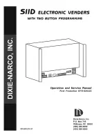
H. 2 MAIN SHAFT & THREAD TEKE-UP COVER COMPONENTS 

REF. NO 

PART. NO 

NAME OF THE PART 

QTY 

10012613 

Coupling 

10009187 

Screw 

10 

10011227 

Rubber ring 

10012615 

Coupling 

10038017 

Engine 

10006157 

Screw ASM. 

10002436 

Screw 

20010974 

Head wheel ASM. 

10012497 

Cog belt 

10 

10006241 

Belt pulley 

11 

10025862 

Bearing 

12 

10012668 

Bearing bush 

13 

10013112 

Driving wheel 

14 

10011062 

Screw 

15 

10025881 

Bearing 

16 

10012607 

Crank 

17 

10010082 

Screw 

18 

10005020 

Screw 

19 

10010545 

Screw 

20 

10012663 

Main shaft 

21 

10036288 

Needle DB × 1 14 #


22 

10013181 

Thread guide 

23 

10013182 

Screw 

24 

10022347 

Needle bar ASM. 

25 

10005745 

Closing ring 

26 

10013590 

Screw 

27 

10030286 

Screw 

28 

10010590 

Joint pin 

29 

10022346 

Thread take -up lever Asm . 

30 

10005785 

Connecting rod ASM. 

31 

10010586 

Sliding block 

32 

10010537 

Screw 

33 

10023444 

Crank 

34 

10003607 

Bearing 

11 

35 

10005791 

Thread take -up lever 

36 

10009784 

Bearing 

37 

10005794 

Pin 

38 

10010083 

Screw 

39 

10005788 

Connecting rod 

40 

10005786 

Washer 

41 

10005747 

Bearing 

Содержание GARUDAN GF-1107-147 MH

Страница 1: ...Instructions for use GF 1107 147 MH ANITA B SRO Průmyslová 2453 7 680 01 Boskovice Czech Republic tel 420 516 454 774 420 516 453 496 fax 420 516 452 751 e mail info anita cz MP02300EN_220518 ...

Страница 2: ...ded table of parameters modified description merging with the engine 24 2 2022 Bohdan Paar MP02300EN_220518 Corection of bobin part number 18 05 2022 Doubek Lumír All rights reserved Owned by Anita B s ro and protected by copyright Use of this content without the written permission of Anita B s ro is prohibited Copyright Anita B s ro 201 7 ...

Страница 3: ...the needle 14 C 6 Inserting the spool into the hook housing 14 C 7 Stitch length adjustment 15 C 8 Foot pressure 15 C 9 Threading the upper thread 15 C 10 Lowering the lower thread 16 C 11 Thread tension 17 C 11 1 Setting the upper thread tension 17 C 11 2 Setting the bobbin thread tension 17 C 12 Threading 18 C 12 1 Thread tension change 18 C 12 2 Adjusting the stiffness of the thread tension com...

Страница 4: ...tilt adjustment 27 E 9 3 Adjusting the feed cams 28 E 10 Adjusting the presser foot pressure and stroke height 29 F MACHINE HANDLING 31 G INSTRUCTIONS FOR THE DRIVE UNIT 32 G 1 Technical parameters 32 G 2 Safety precautions 32 G 3 Using the control panel 33 G 4 Setting user parameters 36 G 5 List of error messages 39 H SPARE PARTS CATALOG 40 ...

Страница 5: ...economical servomotor and LED lighting Thread cutting programmable sewing and foot stroke are controlled using the keyboard on the machine Central lubrication with a dry needle bar prevents possible contamination of the product from oil The use of the machine is mainly when sewing medium to thick materials There is equipment for the machine the use of which and the adjustment of the machine can on...

Страница 6: ...achine head 300 x 135 mm Machine motherboard size 515 x 180 mm Machine power consumption 550 W Floor plan dimensions of the machine including base 1070 x 550 mm Table top height 600 800 mm Machine height including thread stand 1530 mm Equivalent sound pressure level at 50 machine utilization and standard sewing conditions 73 dB A Maximum sewing speed 4 000 stitches min Per needle Nm 90 the machine...

Страница 7: ...machine in any way that could endanger safety If the safety label is damaged order a new one from our company and place it in its original place Be careful not to get caught by the moving mechanisms of the machine especially the sleeves loose parts of clothes and hair Do not work on the machine under the influence of alcohol or drugs B 2 Safety instructions on delivery Follow the markings on the p...

Страница 8: ...vice work with the power supply switched off A Do not use the machine when the electrical voltage exceeds the tolerance of 10 B For safe operation of the machine use the machine under the following conditions working temperature 5 to 40 C storage temperature 10 to 60 C C Humidity in the range of 20 80 relative humidity B 6 Conditions of electrical installation of the machine A Electrical power The...

Страница 9: ...ator Giant No 2 Insert the entire oil sump into the plate cut out Giant No 3 Remove the red plug from the vent valve Giant No 4 Insert 4 pieces of rubber into the corners of the oil pan Caution Excessive oil consumption could occur if the machine is operated with the valve plug not removed Giant No 5 Insert the rubbers into the cut out of the plate put on the hinge and place the whole machine in t...

Страница 10: ...ke of the foot using the knee lever is 10 mm 2 if you need to set a larger stroke max 15 mm adjust with a one screw Note Do not operate the sewing machine when the foot is raised 10 mm or more from the needle bar in contact with the presser foot C 3 Installing the thread stand 1 Assemble according to figure no 7 2 Insert the stand into the hole in the right rear corner of the plate and secure the ...

Страница 11: ...d support it with the foot lift solenoid against the plate 2 Remove the plug from hole and fill the container with the oil supplied with the machine 3 The oil level should reach the marked oil tank line If it is filled with oil inadequately proper lubrication will not be performed 4 You can check the oil level on the oil mark and add oil when working with the sewing machine if the oil level is bel...

Страница 12: ...ng procedure If you tighten screw turn the screw clockwise the amount of oil in the hook will increase If you turn the screw counterclockwise the amount of oil in the hook will decrease Attention 1 When using an RP hook dry head hook for type SS make sure that the screw is as low as possible so as to reduce the amount of oil in the hook 2 Never drain oil from the oil tank even when the RP hook dry...

Страница 13: ...amount of oil supplied b Carry out the above check three times to fine tune the supplied oil Only then adjust the amount of oil supplied by turning the screw 1 If the amount of oil is too small the hook may seize and damage the machine If the amount of oil is large it may splash on the sewn material C 4 2 2 Setting the amount of oil supplied By turning the screw clockwise the amount of oil supplie...

Страница 14: ...nsert the needle into the needle bar so that the grip groove A points towards B 3 Insert the needle into the hole in the needle bar in the direction of the arrow push the needle as far as it will go 4 Tighten screw 5 Check that groove C is on the left side in direction D C 6 Inserting the spool into the hook housing 1 Insert the spool into the hook housing so that the spool rotates in the directio...

Страница 15: ...al counterclockwise C 8 Foot pressure Warning Caution risk of injury switch off when adjusting the machine main switch 1 Loosen nuts Turning regulator clockwise direction A will increase the pressure 2 By turning the regulator counterclockwise direction B the pressure is reduced 3 After adjustment tighten nut 4 In general the standard height is 32 to 34 mm 4 5 kg C 9 Threading the upper thread War...

Страница 16: ...er turning it clockwise 3 Push the lever in direction A and start the sewing machine The bobbin rotates in the C direction and the lower thread is wound As soon as the spool is wound winding ends automatically 4 When removing first tilt the holder and then remove the case 5 To adjust the coil winding loosen screw and move lever in direction A or B Then tighten screw Direction A Decrease direction ...

Страница 17: ...n direction B will make the thread longer 3 By turning the tensioner clockwise direction C the thread tension will be greater 4 By turning the tensioner counterclockwise in direction D the thread tension will be lower C 11 2 Setting the bobbin thread tension 1 By turning screw clockwise direction E the thread tension will be greater 2 By turning screw counterclockwise in direction f the thread ten...

Страница 18: ...he thread tension increases 3 Turn counterclockwise direction B to reduce the voltage C 12 2 Adjusting the stiffness of the thread tension compensating spring 1 Loosen screw and remove thread tension 2 Loosen screw 3 Turn screw clockwise direction A to increase the voltage 4 By turning screw counterclockwise direction B the voltage is reduced ...

Страница 19: ...ANITA MP02300EN_220518 GF 1107 147 MH 19 C 13 Thread guide adjustment Warning Caution risk of injury switch off the main switch when adjusting the machine ...

Страница 20: ...tch off the main when adjusting the machine switch C 14 1 Stop position after thread cutting When the needle stops in the upper position the thread lever must be in the highest position C 14 2 Lower stop position If the needle stops in the lower position the needle reaches the lowest position and returns about 2 mm upwards ...

Страница 21: ...ent turn off the power before starting work Plug Z continuously check the oil level on the U indicator located on the right side of the stand head The minimum and maximum amounts of oil are shown here Top up oil Remove plug Z and pour oil into the hole Now follow the oil indicator U ...

Страница 22: ...ng work E 1 1 Engine rod installation Move the pedal 3 to the right or left as shown by the arrows Engine Speed Sensor Lever 1 and the rod 2 should be perpendicular to the pedal E 1 2 Adjusting the pedal angle The inclination of the pedal can be easily adjusted by changing the length of the rod Loosen the adjusting screw 4 and set the desired rod length ...

Страница 23: ...t of the pedal hard the machine will run at high speed A 3 If you return the pedal to its original position the machine will stop C 4 If you fully depress the back of the pedal the machine will cut the thread and raise the foot D E 2 Back button function 1 During sewing press the reverse button 1 This will reverse the sewing process as long as the button is pressed 2 To lower the position of the b...

Страница 24: ...edle bar with the lower end of the housing 6 and tighten the screw 5 Finally put on the rubber cover 4 Fig No 31 E 5 Adjusting the hook handle Align the lower mark on the needle bar 1 with the lower end of the housing 6 Loosen the screws 2 Adjust the hook tip 3 to the needle axis The distance of the hook tip from the needle must be set to 0 05mm 0 10mm Finally tighten the screws 2 Fig No 31 E 6 Th...

Страница 25: ...ve the stitch plate and the two screws 2 Install a new knife 1 tighten the screws 2 and the stitch plate Fig 33 E 7 2 FIXED KNIFE REPLACEMENT A Remove the screw 2 along with the washer 3 and thumb 4 Finally remove the screw 5 and remove the fixed blade 1 Proceed in the opposite way for mounting Fig No 34 B When dulling the knife sharpen it with a grinding stone according to Fig 35 ...

Страница 26: ...into the recess in the cam If not loosen the screws 2 and perform the correct timing 2 When the roll is retracted trimming in progress be sure to adjust the clearance between the roll and the cam 0 6 0 8 mm At rest there must be a clearance of 0 5 mm between the roller and the cam 3 Adjust the blade of the movable knife 8 so that it is 0 2 to 0 5 mm behind the fixed knife 7 in its last stroke 4 Ad...

Страница 27: ...ition the standard height from the surface of the stitch plate to the top of the feeder is 0 6 mm 0 7 mm for fine materials 0 75 mm 0 85 mm for medium and 1 0 mm 1 2 mm for thick materials E 9 2 Feeder tilt adjustment The inclination of the feeder is adjusted by turning the eccentric of the feeder body A in the direction of the arrow with a screwdriver after loosening the screw B Turning clockwise...

Страница 28: ...02300EN_220518 E 9 3 Adjusting the feed cams Warning Caution risk of injury switch off the main when adjusting the machine switch Use screws and to adjust the feeder ellipse Follow indicators and The ideal ellipse is at point 0 ...

Страница 29: ...ht of the foot increases with the stroke of the pressure rod holder Manually lift the foot with the lever 5 to set the 5 5 mm distance between the lower edge of the foot and the upper edge of the stitch plate B By turning the screw 6 clockwise the presser foot pressure increases and conversely by turning the screw counterclockwise the presser foot pressure decreases After adjustment tighten the nu...

Страница 30: ...e switched to this feed mode This method of administration is suitable for sewing weaker materials that do not slide one after the other The material is only moved by the feeder when the needle is out of the material Under the front cover you will find the handle No 2 which selects the mode If it is connected to lever no 1 the machine is in immersion and needle feed mode If the No 2 rod is connect...

Страница 31: ...LING CAUTION when carrying or positioning the sewing machine If you need to move the machine head always do it in two people Prepare a clean level and firm surface for the machine Do not place the machine on the edge of the table there is a risk of falling ...

Страница 32: ...peed and check the direction of rotation 9 Switch off the engine in the following situations 1 Connect or disconnect connectors on the control panel 2 Threading 3 Unfolding the machine head 4 Repair or any mechanical adjustment 5 Leaving the machine 10 Repairs and thorough maintenance may only be performed by a trained specialist 11 Only spare parts supplied or approved by the manufacturer may be ...

Страница 33: ...he value when setting the parameter value Enter parameters return without saving With the machine idling press this key to enter the user parameter setting mode To enter the advanced parameter setting mode turn off the machine press and hold the key then turn on the machine Parameter setting confirmation Basic display used to go to the parameter settings of the selected program Select user paramet...

Страница 34: ...n or vice versa Position of the presser foot after stopping Press the key for 3 seconds until the corresponding LED lights up the foot goes up automatically when the engine is stopped Press the key for 3 seconds until the corresponding LED goes out the foot remains down when the engine is stopped Position of the presser foot after cutting Press the key for 3 seconds until the corresponding LED lig...

Страница 35: ...ANITA MP02300EN_220518 GF 1107 147 MH 35 Activation is signaled by individual LEDs above the display the order of the LEDs corresponds to the order of the buttons ...

Страница 36: ...h correction function ON OFF HE ON Automatic end stitching function after the last stitch of program sewing Turning on cancels the stitch correction function OFF End stitching will not be performed automatically after stitching but can be triggered manually by the pedal P11 Sew mode selection J B J J The reverse function is activated when the machine is running or stopped B The reverse function is...

Страница 37: ...t value can cause abnormal motor behavior P31 Torque force of the motor when cutting threads 30 P32 Barrier stitch alignment 5 0 200 95 Part A C barrier compensation 0 200 gradual delay P33 Barrier stitch alignment 6 0 200 155 Part B D barrier compensation 0 200 gradual delay P34 Program sewing mode selection A M AND A Program stitching starts automatically when the pedal is depressed M Pedal oper...

Страница 38: ...on P42 Information display N01 Control system version N02 Operator panel version N03 Speed N04 Pedal AD N05 Angle of rotation upper position N06 Angle of rotation lower position N07 AD voltage N12 Knee lever sensor position AD P43 Direction of motor rotation CCW CW CCW CW Clockwise CCW Counterclockwise ...

Страница 39: ...hat the mains voltage is within the correct range and that the speed is not set too high If the error persists replace the control box or call for service E8 Manual return takes longer than 15 seconds It may only be a one time reaction of the return solenoid try restarting the machine If error E8 persists check the manual return lever for damage E9 E11 E14 Position sensor signal error Check the co...

Страница 40: ...ANITA 40 GF 1107 147 MH MP02300EN_220518 H SPARE PARTS CATALOG H 1 MACHINE FRAME MISCELLANEOUS COVER COMPONENTS 1 2 ...

Страница 41: ...ront Plate 1 15 10013706 Slide Plate ASM 1 16 10022846 Face Plate Packing 1 17 20006907 Pace Plate 1 18 10008972 Screw SM3 16 x28 L 10 3 19 10005468 Face plate Adorning 1 20 10008977 Rubber Plug 2 21 10008937 Arm Thread Guide B 1 22 10008973 Screw SM11 64 x40 L 6 1 23 10012142 Screw SM15 64 x28 L 9 2 24 10004374 Screw SM11 64 x40 L 4 8 2 25 10004373 Ruler Stop Seat 1 26 10010593 Screw SM15 64 x28 ...

Страница 42: ...ANITA 42 GF 1107 147 MH MP02300EN_220518 H 1 MACHINE FRAME MISCELLANEOUS COVER COMPONENTS 2 2 ...

Страница 43: ...r Plug 1 39 10012139 Rubber Ring 1 40 10012141 Air discharging 1 41 10012867 Thread Tension Guide 1 42 10011313 Screw M6x12 2 43 10022344 Reverse Feed Solenoid Base 1 44 10013621 Reverse Feed Lever Stopper 1 45 10012149 Screw 1 46 10008936 Saftey Label 1 47 10006157 Screw 4 48 10038018 Controll Box 1 49 10022342 Rulley Cover 1 50 10022848 Rlate 1 ...

Страница 44: ...ANITA 44 GF 1107 147 MH MP02300EN_220518 H 2 MAIN SHAFT THREAD TEKE UP COVER COMPONENTS ...

Страница 45: ...5 10025881 Bearing 1 16 10012607 Crank 1 17 10010082 Screw 1 18 10005020 Screw 2 19 10010545 Screw 1 20 10012663 Main shaft 1 21 10036288 Needle DB 1 14 1 22 10013181 Thread guide 1 23 10013182 Screw 1 24 10022347 Needle bar ASM 1 25 10005745 Closing ring 1 26 10013590 Screw 2 27 10030286 Screw 1 28 10010590 Joint pin 1 29 10022346 Thread take up lever Asm 1 30 10005785 Connecting rod ASM 1 31 100...

Страница 46: ...ANITA 46 GF 1107 147 MH MP02300EN_220518 H 3 HORIZONTAL FEED VERTICAL FEED AND HOOK DRIVING SHAFT COMPONENTS 1 2 ...

Страница 47: ...ing 1 12 10032116 Feed rocker shaft 1 13 10010066 Screw 1 14 10031259 Finger positioning 1 15 10012536 Oil seal 1 16 10012492 Crank 1 17 10013015 Screw 1 18 10010096 Pin 1 19 10005746 Feed adjusting 1 20 10010506 Screw 2 21 10012495 Rubber plug 2 22 10012532 Pin 2 23 10010087 Pin 1 24 10012459 Pin 1 25 10013590 Screw 5 26 10010075 Connecting plate 2 27 10012537 Connecting plate 2 28 10010071 Screw...

Страница 48: ...ANITA 48 GF 1107 147 MH MP02300EN_220518 H 3 HORIZONTAL FEED VERTICAL FEED AND HOOK DRIVING SHAFT COMPONENTS 2 2 ...

Страница 49: ...10012501 Bearing bush 1 46 10010065 Screw 2 47 10005750 Cam 1 48 10010083 Screw 2 49 10005789 Crank 1 50 10012498 Pin 1 51 10005790 Closing ring 2 52 10005744 Bearing 1 53 10012503 Cover plate 1 54 10012534 Hook driving shaft 1 55 10010063 Oil wick 1 56 10010064 Screw 1 57 10012554 Gear 1 58 10012678 Shaft sleeve 1 59 10012423 Oil seal 1 60 10026221 Bearing 1 61 10012585 Bearing bush 1 62 10014503...

Страница 50: ...ANITA 50 GF 1107 147 MH MP02300EN_220518 H 4 HANG LIFTER TENSION RELEASE COMPONENTS ...

Страница 51: ...ing line ASM 1 16 10012130 Screw 3 17 10012445 Wire holder 2 18 10033588 Base plate 1 19 10012181 Screw 1 20 10022854 Tension Release Return 1 21 10003248 Closing ring 1 22 10022508 Spring 1 23 10030397 Connecting rod vertical 1 24 10005881 Fixing shutter 1 25 10012621 Screw 2 26 10022853 Lifting lever link 1 27 10010649 Closing ring 2 28 10012429 Guide plate 1 29 10012637 Screw 1 30 10005685 Hand...

Страница 52: ...ANITA 52 GF 1107 147 MH MP02300EN_220518 H 5 THE NEEDLE BAR SWING COMPONENTS ...

Страница 53: ...iving crank front 1 11 10004611 Screw SM3 16 28 L 12 1 12 10022338 Bushing 1 13 10022356 Needle feed shaft 1 14 10011284 collar 2 15 10022339 Bushing 1 16 10012014 Screw M 5 4 2 17 10010030 Screw SM 3 16 28 L 12 2 18 10012855 Nut M6 3 5 2 19 10022357 Needle feed rod cpmpl 1 20 10022359 Washer 2 21 10022353 Needle feed rod cpmpl 1 22 10014106 Bearing 1 23 10022358 Screw 1 24 10022858 Screw 1 25 100...

Страница 54: ...ANITA 54 GF 1107 147 MH MP02300EN_220518 H 6 FEED ADJUST MECHANISM COMPONENTS ...

Страница 55: ...10012620 Nut 1 16 10007795 Oil pipe 1 17 10031476 Spring 1 18 10012418 Connecting pin 1 19 10040562 Connecting plate 1 20 10012635 Pin 1 21 10013866 Pin 1 22 10010106 Nut 1 23 10010643 Screw SM9 64 x40 L 6 2 24 10012583 Adjustor 1 25 10012626 Shaft sleeve 1 26 10008862 Screw SM1 4 x40 L 5 8 2 27 10012428 Closing ring 1 28 20000150 Crank ASM 1 29 10012638 Crank 1 30 10010095 Screw 1 31 10010287 Pin...

Страница 56: ...ANITA 56 GF 1107 147 MH MP02300EN_220518 H 7 PRESSER FOOT COMPONENTS OF OIL PLATE KNEE LIFT ...

Страница 57: ...9 10008450 Knee pressing shaft I 1 10 10002559 Snap ring 3 11 10012677 Spring 1 12 10008465 Screw 2 13 10008464 Connecting Plate 1 14 10003890 Nut 6 15 10003895 Screw 2 16 10003898 Screw 2 17 10008463 Connecting Rod I 1 18 10008466 Knne pressing shaft II 1 19 10008383 Connecting Rod II 1 20 10009985 Knee pressing plate ASM 1 21 10003894 Screw 1 22 10003897 Knee pressing plate holder 1 23 10003901 ...

Страница 58: ...ANITA 58 GF 1107 147 MH MP02300EN_220518 H 8 BOBBIN WINDER COMPONENTS ...

Страница 59: ...R COMPONENTS REF NO PART NO NAME OF THE PART QTY 1 10013875 Bobbin winder ASM 1 2 10008773 Rubber ring 1 3 10004380 Screw 3 4 10013269 Screw 2 5 10011149 Thread cutter 1 6 10013064 Bobbin thread tension ASM 1 7 10011158 Screw 1 8 10011200 Thread guide plate 1 ...

Страница 60: ...ANITA 60 GF 1107 147 MH MP02300EN_220518 H 9 AUTOMATIC REVERSE FEED COMPONENTS ...

Страница 61: ... 61 H 9 AUTOMATIC REVERSE FEED COMPONENTS REF NO PART NO NAME OF THE PART QTY 1 10008934 Screw 1 2 10038021 Option Switch ASM 1 3 10034506 ASM electromagnet 1 4 10012142 Screw 2 5 10012587 Washer 1 6 10012628 Crank Pin 1 7 10013538 Screw 1 ...

Страница 62: ...ANITA 62 GF 1107 147 MH MP02300EN_220518 H 10 THREAD STAND COMPONENTS ...

Страница 63: ...2953 Nut M5 5 7 10004289 Thread Guide Pipe 1 8 10004285 Thread Guide Bushing 1 9 10004298 Thread Hanger Upper 1 10 10004286 Column Pipe Connector 1 11 10004291 Column Pipe Lower 1 12 10004290 Washer 16 30 1 5 2 13 10004295 Washer 16 5 27 5 3 2 14 10002953 Nut M5 1 15 10004288 Spool 2 16 10004287 Spool Cushion 2 17 10004281 Soft Cushion Of Thread Plate 2 18 10004299 Thread Plate 2 19 10003312 Screw...

Страница 64: ...ANITA 64 GF 1107 147 MH MP02300EN_220518 H 11 WIPER COMPONENTS ...

Страница 65: ...ANITA MP02300EN_220518 GF 1107 147 MH 65 H 11 WIPER COMPONENTS REF NO PART NO NAME OF THE PART QTY 1 10034507 Wiper ASM 1 2 10012631 Screw 2 ...

Страница 66: ...ANITA 66 GF 1107 147 MH MP02300EN_220518 H 12 THREAD TRIMMER COMPONENTS ROTATION KNIFE 1 2 ...

Страница 67: ...13010 Crank Block 1 14 10010595 Screw M4x7 5 2 15 10013023 Fixed Plate 1 16 10009626 Screw M3x4 35 3 17 10013026 Knife Holder 1 18 10011588 Screw SM1 1 6 4 40 L 4 7 2 19 10011494 Round Knife 1 20 10013045 Round Knife Bracket 1 21 10011578 Nut 1 22 10010736 Thread Trimmer Cam 1 23 10013465 Screw SM1 4 40 L 1 0 2 24 10013030 Spring 1 25 10014462 Bushing 1 26 10012162 Screw M5x5 1 27 10013008 Washer ...

Страница 68: ...ANITA 68 GF 1107 147 MH MP02300EN_220518 H 12 THREAD TRIMMER COMPONENTS ROTATION KNIFE 2 2 ...

Страница 69: ...NO NAME OF THE PART QTY 38 10011605 Screw SM1 4 x28 L 12 1 39 10009471 Nut M4 2 40 10006131 Solenoid Base 1 41 10013046 Solenoid Connecting Shaft 1 42 10011845 Washer 1 43 10011606 Washer 1 44 10006137 Thread Trimmer Solenoid 1 45 10013590 Screw SM11 64 x40 L 4 1 46 10008834 Spring 1 47 10012467 Screw 1 ...

Страница 70: ...ANITA 70 GF 1107 147 MH MP02300EN_220518 H 13 OIL LUBRICATION COMPONENTS ...

Страница 71: ...08785 Pipe stopper 2 12 10007800 Oil pipe 1 13 10007800 Oil pipe 1 14 10008101 Oil wick 1 15 10012160 Pipe stopper 2 16 10030182 Oil connection ASM 1 17 10013012 Nut 1 18 10007800 Oil pipe 1 19 10007800 Oil pipe 1 20 10008781 Pipe stopper 2 21 10008779 Oil connection 1 22 10008783 Screw 1 23 10010240 O ring 1 24 10008972 Screw 2 25 10009469 Washer 2 26 10012669 Oil tank ASM 1 27 10013025 Screw 1 2...

Страница 72: ...ANITA 72 GF 1107 147 MH MP02300EN_220518 H 14 ACCESSORIE PART COMPONENTS ...

Страница 73: ...ew Driver Middle 1 5 10013185 Screw Driver Small 1 6 10005639 Needle Thread ASM Guide 1 7 10010994 Screw Driver Large 1 8 10005776 Frame Vinyl Cover 1 9 B Accessory Bag ASM B 1 10 10006286 Rubber Cushion 2 11 10013113 Oil Reservior Seat 2 12 10003889 Nail 6 13 10004466 Hinge Compl 2 14 10013101 Oil Reserve Cushion 2 15 10025484 Bobbin 3 16 10013294 Oiler ASM 1 17 10004455 Oil Box 1 18 10034917 Nee...

Отзывы: