User’s Manual for Node G
Network Elements
Page 30
M0121A2A.doc
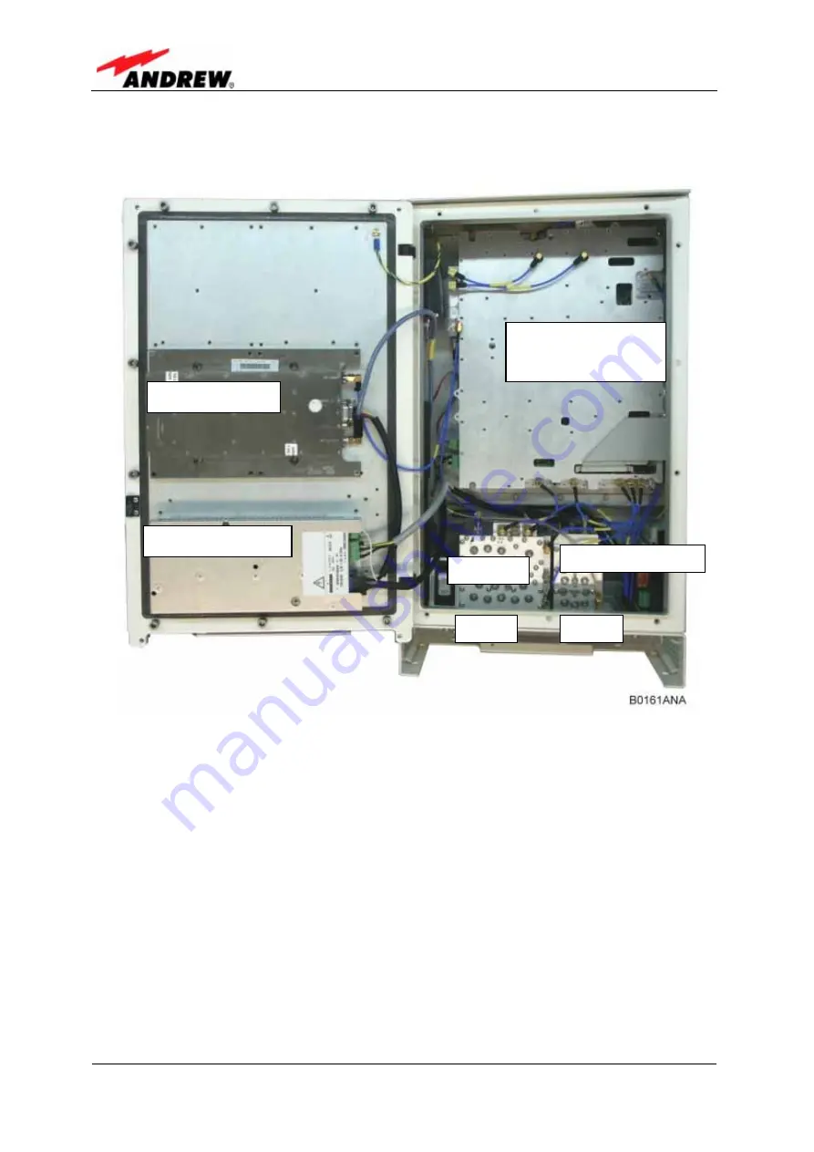
Using a Node G x30 as an example, the following figure illustrates the positions of
the RF components inside the Node G.
figure 4-2 RF path of a Node G x30, exemplary
DL final amplifier
Power supply unit
Duplexer with LNA
Digital channel
module with
integrated controller
Duplexer
UL IN
DL IN
Содержание Node G 930
Страница 1: ...ID No 7164491 Page 1 User s Manual for Node G Network Elements ...
Страница 12: ...User s Manual for Node G Network Elements Page 12 M0121A2A doc For your notes ...
Страница 16: ...User s Manual for Node G Network Elements Page 16 M0121A2A doc For your notes ...
Страница 28: ...User s Manual for Node G Network Elements Page 28 M0121A2A doc For your notes ...
Страница 52: ...User s Manual for Node G Network Elements Page 52 M0121A2A doc For your notes ...
Страница 53: ...6 Illustrations ID No 7164491 Page 53 6 ILLUSTRATIONS 6 1 CABINET DRAWINGS figure 6 1 Cabinet of a Node G ...
Страница 55: ...6 Illustrations ID No 7164491 Page 55 figure 6 3 Layout of the Node G x38 exemplaryx30 exemplary ...
Страница 56: ...User s Manual for Node G Network Elements Page 56 M0121A2A doc For your notes ...
Страница 62: ...User s Manual for Node G Network Elements Page 62 M0121A2A doc For your notes ...


