


9
Anderson Greenwood
SerieS 5200 POSrV
InstallatIon and MaIntenance InstructIons
3.1 pilot disassembly
3.1.1
To facilitate re-assembly, place all parts
removed in an orderly arrangement so that the
correct parts can be assembled in the proper
sequence.
3.1.2
remove cotter pin (32), lever pin (31) and
lifting lever (30). remove the lift lever cap screw
(35) and cap (29). Loosen hex nut (34)* from the
spindle nut (33) and remove the spindle nut.
* For pilots using cotter pin (prior design)
instead of hex nut to retain spindle nut, refer
to cotter pin conversion instruction sheet
1101-27480 for replacement part numbers and
procedure to replace cotter pin with hex nut.
3.1.3
remove lock nut (26) and completely
loosen the pressure adjustment screw (25).
remove the bonnet ring screw (21), bonnet ring
(20) and bonnet (19). remove bonnet ring by
using a ⅜-16 UNC-2A bolt approximately 2½”
long and use as a handle (or use a spanner
wrench). (Note: be careful not to drop the
spring (22), spring washers (23 and 24) and
lifting rod (27) when removing the bonnet).
3.1.4
Slide the lifting rod bushing (28) and lifting
rod through the spring washers and spring.
3.1.5
remove four piston plate screws (38)
and remove the piston plate (11) with attached
sense piston (12), piston seal (17), piston
connector (2), inlet seat (3), inlet nozzle (14),
exhaust seat retainer (4), exhaust seat (37) and
exhaust seat stem (5). remove and discard
body/piston plate seal (40).
3.1.6
remove bushing (13) using a ½” hex drive.
3.1.7
Place pilot on its side and remove the ½”
pipe plug (42) from the bottom of the valve. With
a brass, ⅜” diameter, flat end rod and hammer,
gently tap through the bottom hole and push
the spool/body O-ring seals (39), dome spool
(15), dome seal (18), dome seal backup ring
(16), exhaust nozzle (6), exhaust washer (7),
stem seal (36) and stop washer (8) out of body.
Discard spool/body O-rings, stem seal, dome
seal and dome seal backup ring.
note:
If dome spool (15) and exhaust nozzle (6) are
difficult to separate, place exhaust nozzle into a soft
jawed vice. Using a flat end brass bar hold it next
to the dome spool and gently tap using a hammer.
Be careful not to scratch or damage the parts.
3.1.8
Unscrew the sense piston from the piston
connector by placing an open end wrench
onto the flats on both parts (use soft jawed
vice to hold sense piston if available). Use an
acetone based solution to remove the Loctite
242 solution from the threads. Slide the piston
connector through the piston plate. Holding the
3.2 pilot assembly
During assembly it must be observed that all
moving parts are free to move throughout their
full travel without any binding.
3.2.1 Inlet seat/nozzle lapping
A slightly worn inlet seat and nozzle may be
repaired by lapping. if either part is 'washed-
out', they must be replaced with new parts,
which must be lapped as follows:
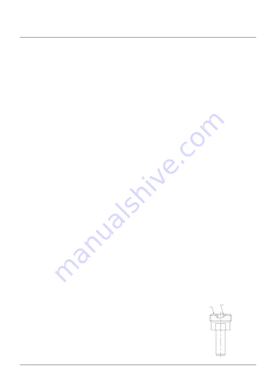
• Before starting the lapping process, inspect
the radius and finish shown on the below
sketch of the inlet nozzle. The sharp corner is
attained by lapping the entire top surface of
the nozzle to the specified finish.
• Place inlet seat through inlet nozzle. Apply
small amount of Hyprez 3L diamond lapping
compound or equal to the inlet seat’s conical
surface. Hold the inlet nozzle in one hand
and lightly lap the inlet seat with the inlet
nozzle by spinning the inlet seat onto the inlet
nozzle’s seating surface. Minimum force shall
be applied during this process.
• Start with coarse Hyprez lapping compound.
Be careful and use this for a brief amount
of time as it will remove material quickly.
Wipe clean with solvent such as acetone and
repeat with fine Hyprez lapping compound(s)
as required. Note that this process may take
up to 15 minutes or more. Take care to not
remove material from the parts when lapping.
3.2.2
Clean the inlet seat and nozzle by
removing the lapping compound using Varsol
followed by Acetone. Afterwards, wipe with
a clean lint-free cloth or towel. When dry,
the seating surface should be examined to
verify if an acceptable sealing surface has
been achieved. A proper surface is one which
exhibits a dark gray appearance with no visible
scratches across the entire lapping surface.
flats on the inlet nozzle and piston connector,
unthread piston connector from inlet nozzle and
remove inner spring (10) and outer spring (9).
warning:
remove piston seal from sense piston
carefully to prevent scratching the sealing
surface (O.D.) of piston. Discard piston seal.
3.1.9
insert a ⅛” hex drive into top of inlet seat
and with another ⅛” hex drive insert into the
bottom of the exhaust seat stem and unthread.
Separate the exhaust seat retainer from the
inlet seat. remove exhaust seat from exhaust
seat retainer and discard exhaust seat. Use
an acetone based solution to remove the
Loctite 242 solution from the threads.
3.2.3 Inlet seat and exhaust seat sub assembly
Carefully examine the exhaust seat to verify if
one side is concave and the other side is flat.
Place the inlet seat through the inlet nozzle.
Slide the exhaust seat retainer onto the inlet
seat. Slide the exhaust seat with the flat face
down onto the exhaust seat stem. Place a small
amount of Loctite 242 on the threads of the
inlet seat. Thread the exhaust seat stem onto
the inlet seat, squeezing the exhaust seat into
the exhaust seat retainer. Using a ⅛” hex drive
that is on top of the inlet seat and the exhaust
stem, tighten the inlet seat onto the exhaust
stem. (Be careful not to over tighten, as this
may cause damage to the parts.)
3.2.4
Place the stem seal with the opening
of the cup facing outward into the exhaust
washer. Place stop washer into body cavity with
the raised face up. Place body/spool O-ring
seal into body cavity on top of the stop washer.
Place exhaust washer into body cavity with the
U-cup seals facing down into the cavity. Place
exhaust nozzle into body cavity with the larger
open end facing downward next to the exhaust
washer. Place another body/spool O-ring seal
into cavity.
3.2.5
Place back-up ring into dome spool. Next
place dome seal on top of back-up ring with the
opening of the dome seal facing up. Place dome
spool into body cavity with dome seal facing
up. Place final body/spool O-ring seal into
body cavity. Apply a light coating of Fluorolube
LG-160 oil or equivalent on threads of bushing.
Thread bushing (13) into body and tighten until
spool set is compressed fully metal-to-metal.
Lapped surface
4 ra finish
radius .005 max


