Andersen RA2028001300 Скачать руководство пользователя страница 7

p7

E1 Single Speed Electric Motor Unit, 12V & 24V 

To Suit Self-Tailing Winch Sizes 28,34,40

INSTALLATION INSTRUCTIONS
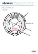
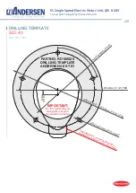
STEP 3

Motor unit

lifting eye bolt

Correct mating of drive shaft 

housing top flange with 

underside of deck plate

Incorrect mating of drive 

shaft housing top flange with 

underside of deck plate

*Note:

 It is extremely important that the motor is aligned correctly with the winch.  

Non-aligned motors will be noisy and gear wear will be accelerated. 

*Note:

 It is important that two or more people are involved with Step 3.

• 

Remove clamping ring [5] from drive shaft  housing [16] of motor unit. 

• 

Fit the supplied M6 eye bolt [A6] to the top of the motor drive shaft [12] and attach a strong  
rope to facilitate lifting the motor unit up into position through the hole in the deck, deck plate  
and clamping ring as shown below.

• 

Using the rope, raise the motor unit so that the drive shaft protrudes through the large hole in  
the deck and deck plate [7]. A lifting device is recommended when raising the motor unit.

• 

Rotate the motor unit into the required position to suit the under deck cavity, ensuring that the 
motor is aligned properly – The protruding octagonal detail on the drive shaft housing [16] flange 
must fit snugly into the octagonal recess in the deck plate to allow the motor top flange to fit 
flush with the underside of the deck plate [7] (refer to diagrams below).

*Note:

 Ensure that the O-ring 

[8]

 on top of the drive shaft housing 

[16]

 is in place in its groove.

• 

Insure that the locking grub screw [4] in the clamping ring [5] is not protruding beyond the  
upper surface of the clamping ring, when fitting the clamping ring.

• 

Fit and securely tighten the clamping ring [5] using the pin spanner [A8] provided. 

• 

Tighten the locking grub screw [4] when the clamping ring [5] is securely in place. 

*Note:

 Do not use a sealant between the flange and deck plate. An O-ring insures a waterproof 

connection.  Extra waterproofing can be achieved by applying sealant to the top of the deck plate 
around the clamping ring after installation (make sure no sealant comes onto the sealing ring 

[8]

).

90°

5

  Clamping Ring

4

  Grub Screw

5

  Clamping Ring

4

  Grub Screw

Motor flange

Non-aligned hole in 
deck preventing correct 
motor alignment

Inadequate underdeck 
clearance preventing 
correct motor alignment

7

  Deck Plate or 

Winch Base

7

  Deck Plate or 

Winch Base

Grub screw  
protruding too far

Clamping ring  
not parrallel to 
deck plate

Содержание RA2028001300

Страница 1: ... Rev 5 FOR USE WITH Serial No PS______________________ Winch Versions 28 V 3 2 34 V 1 0 40 V 3 4 RA2028001300 RA2028001400 RA2028011300 RA2028011400 RA2028211300 RA2028211400 RA2034001300 RA2034001400 RA2034011300 RA2034011400 RA2034211300 RA2034211400 RA2040001300 RA2040001400 RA2040011300 RA2040011400 RA2040211300 RA2040211400 ...

Страница 2: ..._____________________________________________ 5 Installation instructions_____________________________________ 6 10 Wire circuit breaker battery capacity requirements________ 10 Electrical connection diagram_________________________________11 Troubleshooting___________________________________________ 12 13 Service maintenance_______________________________________ 14 Installation dimensions Sizes ...

Страница 3: ...s always possible by simply inserting a standard winch handle Included in your E1 Electric Motor Kit Motor unit Deck plate 7 Gear wheel 3 Push button incl 500 mm 19 5 8 control cable A1 Push button Gasket A2 5 pcs 4 for 28 34 M6 x 16mm countersunk socket head screws 6 3 pcs 6 x 19 mm screws A9 Eye bolt M6 A6 4 mm Allen key A4 5 mm Allen key A5 Pin spanner 5 mm pins A8 Product manual A10 Drilling t...

Страница 4: ...hown as item 3 in the diagram above will already be fitted inside the winch The gear wheel has a hexagonal section that protrudes from the winch base to engage in the motor unit drive shaft When supplied as an E1 Electric Conversion Kit only this gear wheel is supplied separately and must replace the existing gear wheel in the winch see pages 6 10 for instructions A8 20 3 4 5 6 7 8 9 22 23 10 16 1...

Страница 5: ...ve shaft housing 776100 17 1 Compression bearing 775890 18 1 Ratchet gear wheel 776110 19 1 Key DIN6885 A 8x7x20 20 4 Screw DIN912 A4 M6x55 21 4 Washer DIN125 A4 Ø6 4 22 2 Nut DIN439 A4 M6 23 4 Washer DIN125 A4 Ø6 4 24 2 Screw DIN933 A4 M6X20 25 1 Key DIN6885 A 5x5x15 A1 1 Push button with plastic cover RA582000 A2 1 Push button gasket 735050 A3 1 Drilling template 28 34ST E1 RD100327 A3 1 Drillin...

Страница 6: ...s 15 16 for the minimum motor offset dimensions at the various positions Placing the deck plate on the motor unit in the various positions prior to installation can assist with visualising the motor position options Note To ensure the correct functioning of the winch it should be positioned with the correct line entry angle of 3 8 below horizontal Refer to the winch product manual for details of c...

Страница 7: ...g that the motor is aligned properly The protruding octagonal detail on the drive shaft housing 16 flange must fit snugly into the octagonal recess in the deck plate to allow the motor top flange to fit flush with the underside of the deck plate 7 refer to diagrams below Note Ensure that the O ring 8 on top of the drive shaft housing 16 is in place in its groove Insure that the locking grub screw ...

Страница 8: ...ing the self tailing arm and drum Remove the drive shaft from the winch by placing a locking winch handle into the socket at the top of the drive shaft rotating a little each direction and pulling up Remove the upper gear wheel through the upper side window in the base stem Remove the lower side gear wheel shaft retained by the flat st st ring for 28 34ST and grubscrew shaft for 40ST Remove the lo...

Страница 9: ...er tube Or drill a Ø25mm 1 hole at a 2mm offset to the centre of the push button location Refer to the push button drilling diagram below Using the supplied push button gasket A2 as a template drill 3 x Ø3 mm 1 8 mounting holes Ensure the clear breather tube is inserted into the back of the push button Fit gasket A2 and push button A1 in place with hinged cover opening upwards if mounted on vertic...

Страница 10: ...e malfunction of the winch and in worst case FIRE The wires should always be as short as possible 12V DC 24V DC WINCH WIRE LENGTH WIRE SIZE CIRCUIT BREAKER ADDITIONAL BATTERY CAPACITY PER WINCH MIN TOTAL BATTERY BANK CAPACITY WIRE SIZE CIRCUIT BREAKER ADDITIONAL BATTERY CAPACITY PER WINCH MIN TOTAL BATTERY BANK CAPACITY 28 ST E1 0 3 m 0 10 ft 35 mm 150 A 114 Ah 300Ah 25mm 70 A 60 Ah 150Ah 3 8 m 10...

Страница 11: ...internal fuse will blow and need to be replaced See page 12 for instructions WARNING PUSH BUTTON Push button cable 1 Blue Switch 3 Blue Black Ground 4 Red LED STANDARD CONNECTION PUSH BUTTON CABLE MOTOR CABLE 1 Blue 1 Brown 3 Blue Black 3 Green 4 Red 4 Yellow Wires are marked with numbered sleeves 3 1 5 2 4 1 3 6 4 Motor cable 1 Brown Switch 1 2 White Switch 2 used for 2 speed motors only 3 Green ...

Страница 12: ...over using a 1 Phillips head screw driver refer to picture below Rotate the outer motor outer cover slightly and carefully pull the motor cover away from the motor unit Note After the first 5mm 3 16 the O ring will release the cover there will be no resistance the rest of the way and very little force should be used so as not to damage the internal wiring connections When the outer cover is clear ...

Страница 13: ...stems and 22 Volts for 24V systems 3 Flashes Max temperature of the motor has been reached The motor has overheated Status will automatically reset to normal and the winch will be ready for use when the motor has cooled down sufficiently this may take some time Ensuring adequate ventilation around the motor will help to avoid overheating 4 Flashes Max temperature of the control board has been reac...

Страница 14: ...vicing of internal parts To avoid potential sea water ingress and to maximise the service life of your electric winch motor unit it is recommended to re lubricate the motor unit drive shaft Sealing Ring 9 once a year Under intensive use such as racing charter or blue water sailing we recommend lubrication twice a year To access the Sealing Ring 9 it is necessary to remove the winch from the Deck P...

Страница 15: ...16 161mm 6 5 16 183mm 7 3 16 49mm 1 15 16 Ø64mm 2 17 32 65mm 2 9 16 300mm 11 13 16 Ø136mm 5 3 8 Ø125mm 4 5 16 Ø70mm 2 3 4 75mm 2 15 16 161mm 6 5 16 183mm 7 3 16 49mm 1 15 16 MOTOR OFFSET Minimum Ox 290mm 11 7 16 Oy 149mm 5 7 8 Minimum Oy 141mm 5 9 16 Ox 298mm 11 3 4 Values with motor in optimum position to minimise Ox or Oy Oy value includes allowance for push button cable and fitting on the motor...

Страница 16: ...16 79mm 3 1 8 183mm 7 3 16 183mm 7 3 16 49mm 1 15 16 Ø64mm 2 17 32 65mm 2 9 16 300mm 11 13 16 Ø156mm 6 5 32 Ø152mm 6 Ø75mm 2 15 16 79mm 3 1 8 183mm 7 3 16 183mm 7 3 16 49mm 1 15 16 H J Ox Oy MOTOR OFFSET Minimum Ox 284mm 11 3 16 Oy 132mm 5 3 16 Minimum Oy 124mm 4 7 8 Ox 292mm 11 1 2 Values with motor in optimum position to minimise Ox or Oy Oy value includes allowance for push button cable and fit...

Страница 17: ...4 40 DRILLING TEMPLATE SIZE 28 34 NOT TO SCALE PART NO RD100327 DRILLING TEMPLATE ANDERSEN 28 34 ST E1 IMPORTANT On this model the self tailing arm is fixed in one position as shown 72 TYP HO LE Ø 85m m 3 3 8 Ø120mm 4 23 32 PCD 8mm 5 16 BASE PLATE Ø136mm 5 3 8 PCD HOLE Ø6 5mm 9 32 5 OFF ...

Страница 18: ...TO SCALE PART NO RD100525 DRILLING TEMPLATE ANDERSEN 40 ST E1 IMPORTANT On this model the self tailing arm is fixed in one position as shown 72 TYP HO LE Ø 85m m 3 3 8 Ø130mm 5 1 8 PCD 8mm 5 16 BASE PLATE Ø156mm 6 5 32 PCD HOLE Ø6 5mm 9 32 5 OFF Self tailing arm can be positioned in 8 different positions at 45 increments ...

Страница 19: ...lified to operate an electric winch must be kept at a safe distance from the winch and any rigging or fittings that are under load Long hair and or loose clothing must be tied back to avoid being caught in the winch In the event of a rope override or other fault stop the winch and turn off power before attempting to resolve the problem Avoid Accidental Operation Remove winch handles and turn off p...

Страница 20: ...isit www andersenwinches com Visit www andersenwinches com WORLDWIDE DISTRIBUTION SERVICE WARRANTY E1 Single Speed Electric Motor Unit 12V 24V To Suit Self Tailing Winch Sizes 28 34 40 p20 PRODUCT MANUAL ...

Отзывы: