


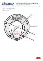
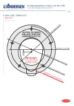

p11
E1 Single Speed Electric Motor Unit, 12V & 24V
To Suit Self-Tailing Winch Sizes 28,34,40
ELECTRICAL CONNECTION DIAGRAM
28/34/40 ST E1 SINGLE SPEED 12V/24V
Positive (+) motor terminal must be
connected to Positive (+) battery terminal.
Negative (-) motor terminal must be
connected to Negative (-) battery terminal.
If polarity is reversed the motor controller
internal fuse will blow and need to be
replaced. See page 12 for instructions.
WARNING
PUSH BUTTON
Push button cable
1. Blue
= Switch
3. Blue Black = Ground
4. Red
= LED
STANDARD CONNECTION
PUSH BUTTON CABLE
MOTOR CABLE
1. Blue
= 1. Brown
3. Blue Black = 3. Green
4. Red
= 4. Yellow
Wires are marked with numbered sleeves
3
1
5
2
4
1
3
6
4
Motor cable
1. Brown = Switch 1
2. White = Switch 2 (used for 2 speed motors only)
3. Green = Ground
4. Yellow = LED
5. Grey = Ratiometric current output
6. Pink
= Low current cutout
DETAIL A
DETAIL A
CIRCUIT BREAKER
BATTERY (12V or 24V)
WINCH MOTOR


