background image

User Guide

EVAL-SSM6515

INSTALLING THE SIGMASTUDIO SOFTWARE

analog.com

Rev. 0 | 7 of 23

The USBi drivers are now installed. Leave the USBi connected to

the PC.

Using Windows 7 or Windows Vista

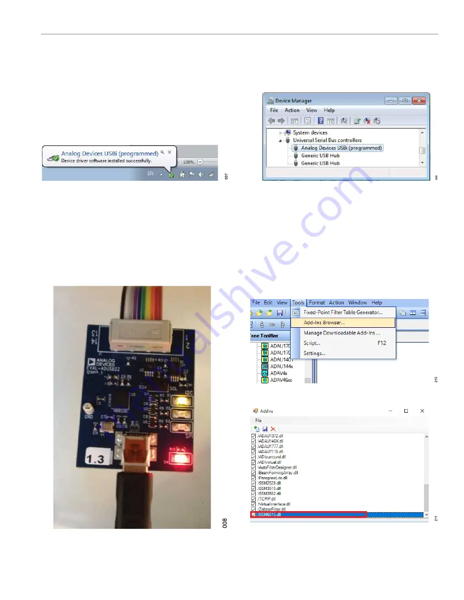
After connecting the USBi to the USB 2.0 port, Windows 7 or

Windows Vista recognizes the device and installs the drivers auto-

matically (see 

Figure 7

). When the installation completes, leave the

USBi connected to the PC.

Figure 7. USBi Drivers Installed Properly

Confirming Proper Installation of the USBi
Drivers

To confirm that the USBi drivers are installed properly, complete the

following steps:

1.

With the USBi still connected to the USB 2.0 port of the PC,

check that both the yellow I

2

C LED and the red power indicator

LED are illuminated (see 

Figure 8

).

Figure 8. State of USBi Status LEDs After Driver Installation

2.

In the Windows 

Device Manager

, under the 

Universal Serial

Bus controllers

 section, check that 

Analog Devices USBi

(programmed)

 appears as shown in 

Figure 9

.

Figure 9. Confirming Driver Installation Using the Device Manager

ADDING THE DLL FILE

Add the provided 

SSM6515.dll

 file manually by copying the

SSM6515.dll

 file to the 

C:\ProgramFiles\AnalogDevices\SigmaS-

tudio

 folder in the PC. To add the SSM6515 to the 

Tree ToolBox

,

click 

Tools

 and then click 

Add-Ins Browser...

 (as shown in 

Figure

10

). The 

AddIns

 popup window opens (see 

Figure 11

).

In the list of devices displayed in the 

AddIns

 popup window, ensure

the 

SSM6515

 checkbox is selected, as shown in 

Figure 11

. Click

File

 and then click 

Save

 before exiting the window.

Figure 10. Adding an SSM6515

Figure 11. Saving the SSM6515.dll File in the AddIns Popup Window

Содержание EVAL-SSM6515

Страница 1: ...AL SSM6515Z can be powered by the USB bus or by a single 3 8 V to 5 V supply These supplies are regulated to the voltages required on the EVAL SSM6515Z The printed circuit board PCB is a 4 layer design with a ground plane and a power plane on the inner layers The EVAL SSM6515Z con tains 0 1 in pitch male headers for connecting to external speakers The minimum speaker load must be 8 Ω The EVAL SSM6...

Страница 2: ... DLL File 7 Setting Up SigmaStudio 8 Setting Up the Evaluation Board 10 Default Switch and Jumper Settings S PDIF Input I2C Mode 10 Powering Up the EVAL SSM6515Z 11 Power 11 Using I2C Control Mode 11 Using SigmaStudio with USBi for I2C Control 11 External I2S Input I2C Mode 13 Default Switch and Jumper Settings PDM Input I2C Mode 13 Default Switch and Jumper Settings S PDIF Input Standalone Mode 1...

Страница 3: ...User Guide EVAL SSM6515 EVALUATION BOARD BLOCK DIAGRAM analog com Rev 0 3 of 23 Figure 2 EVAL SSM6515Z Block Diagram ...

Страница 4: ...e or the PDM_FS of 3 MHz or 6 MHz for AMP2 in PDM standalone mode J22 2 pin header 0 1 in pitch I2C SCL AMP2 Jumper connects the USBi SCL to AMP2 Leave open in standalone mode J23 2 pin header 0 1 in pitch I2C SDA AMP2 Jumper connects the USBi SDA to AMP2 Leave open in standalone mode J24 2 pin header 0 1 in pitch I2C SCL AMP1 Jumper connects the USBi SCL to AMP1 Leave open in standalone mode J25 ...

Страница 5: ...al input J13 I2S Input Selection Header The J13 is a 9 pin header Pin 1 Pin 4 and Pin 7 of J13 are GND whereas Pin 2 Pin 5 and Pin 8 are used as signal inputs The outermost pins Pin 3 Pin 6 and Pin 9 are connected to the S PDIF receiver I2S outputs See Table 2 for the pin connections The I2S signals must be 1 8 V p p Table 2 J13 9 Pin 3 3 Header Connections Pin Signal Test Conditions Comments 1 4 ...

Страница 6: ...oes not function properly with a USB 3 0 port 2 Install the driver software see the Using Windows XP section or the Using Windows 7 or Windows Vista section for more information Using Windows XP After connecting the USBi to the USB 2 0 port Windows XP recognizes the device see Figure 3 and prompts the user to install the drivers Figure 3 Found New Hardware Notification Use the Found New Hardware W...

Страница 7: ...icator LED are illuminated see Figure 8 Figure 8 State of USBi Status LEDs After Driver Installation 2 In the Windows Device Manager under the Universal Serial Bus controllers section check that Analog Devices USBi programmed appears as shown in Figure 9 Figure 9 Confirming Driver Installation Using the Device Manager ADDING THE DLL FILE Add the provided SSM6515 dll file manually by copying the SS...

Страница 8: ...Studio by double clicking the shortcut on the desktop Click File and then click New Project or press Ctrl N to create a new project as shown in Figure 12 The default view of the new project is the Hardware Configuration tab Figure 13 shows a new SigmaStudio project Figure 12 New Project Figure 13 New SigmaStudio Project ...

Страница 9: ...rectly Figure 15 USBi Not Detected by SigmaStudio If SigmaStudio detects the USBi board on the USB port of the PC the background of the USB label is green see Figure 16 Figure 16 USBi Detected by SigmaStudio Add two SSM6515s from the Tree ToolBox to the Hardware Configuration tab by selecting SSM6515 from the Processors ICs DSPs list and dragging it to the project space see Figure 10 To use the US...

Страница 10: ... EVAL SSM6515Z for external I2S input with I2C control using the USBi The EVAL SSM6515Z provides multiple options for configuring the SSM6515 See Table 3 for the I2C mode and device address settings By default the EVAL SSM6515Z is configured for Address 0x34 AMP1 and Address 0x35 AMP2 If other addresses are required refer to Table 3 To use the on board S PDIF receiver I2S input insert jumpers for ...

Страница 11: ...SBi board to J1 control port of the EVAL SSM6515Z POWER Power can be supplied to the EVAL SSM6515Z in one of three ways connecting the EVAL ADUSB2EBZ USBi board to J11 see Figure 20 connecting a 3 8 V dc to 5 V dc power supply to J1 tip positive or using the binding posts J2 5 V and J10 GND If no external supply is used the EVAL SSM6515Z draws power from the USBi board Figure 20 Header J11 Control...

Страница 12: ...log com Rev 0 12 of 23 3 Click the Control Status tab Click Software Master Power down to select Normal to turn on the amplifier if the I2S clocks are provided The amplifier outputs the audio at J38 AMP1 and J40 AMP2 Figure 21 ChipID Tab Figure 22 Datapath Tab ...

Страница 13: ...he J13 header connections Figure 24 External I2S Selection DEFAULT SWITCH AND JUMPER SETTINGS PDM INPUT I2C MODE If using the PDM source as an input use the same settings as shown in Figure 19 but connect only the PDM data and clock at Pin 2 and Pin 8 of J13 Leave Pin 5 center unconnected Follow Table 5 for the desired PDM mode Then use SigmaStudio to configure the PDM mode for the SSM6515 as show...

Страница 14: ...5Z for standalone mode refer to Table 3 and set the desired input I2S or PDM mode using Table 5 Configure J13 accordingly If using the on board S PDIF receiver I2S input insert the jumpers as shown in Figure 18 If using the external I2S input refer to Figure 24 for J13 If using the PDM source connect only the PDM data and PDM clock at Pin 2 and Pin 8 of J13 respectively Leave Pin 5 center unconnec...

Страница 15: ...User Guide EVAL SSM6515 EVALUATION BOARD SCHEMATICS AND ARTWORK analog com Rev 0 15 of 23 Figure 26 EVAL SSM6515Z Schematic Block Diagram HP Is Headphone ...

Страница 16: ...User Guide EVAL SSM6515 EVALUATION BOARD SCHEMATICS AND ARTWORK analog com Rev 0 16 of 23 Figure 27 EVAL SSM6515Z Schematic Page 1 ...

Страница 17: ...User Guide EVAL SSM6515 EVALUATION BOARD SCHEMATICS AND ARTWORK analog com Rev 0 17 of 23 Figure 28 EVAL SSM6515Z Schematic Page 2 ...

Страница 18: ...User Guide EVAL SSM6515 EVALUATION BOARD SCHEMATICS AND ARTWORK analog com Rev 0 18 of 23 Figure 29 EVAL SSM6515Z Layout Top Assembly Figure 30 EVAL SSM6515Z Layout Top Copper ...

Страница 19: ...User Guide EVAL SSM6515 EVALUATION BOARD SCHEMATICS AND ARTWORK analog com Rev 0 19 of 23 Figure 31 EVAL SSM6515Z Layout Ground Plane Figure 32 EVAL SSM6515Z Layout Power Plane ...

Страница 20: ...User Guide EVAL SSM6515 EVALUATION BOARD SCHEMATICS AND ARTWORK analog com Rev 0 20 of 23 Figure 33 EVAL SSM6515Z Layout Bottom Copper ...

Страница 21: ...User Guide EVAL SSM6515 EVALUATION BOARD SCHEMATICS AND ARTWORK analog com Rev 0 21 of 23 Figure 34 EVAL SSM6515Z Layout Fab Drawing ...

Страница 22: ...5 J19 to J21 J33 J35 JP1 3 pin 1 3 single inline position SIP headers Digi Key S1011E 03 ND 1 J11 10 pin 2 5 shroud polarized header Digi Key MHC10K ND 1 J12 RCA jack printed circuit board PCB through hole right angle yellow Connect Tech Products CTP 021A S YEL CP 1403 ND 1 J13 9 pin 3 3 unshrouded header Digi Key A108960 ND 4 J37 to J40 4 pin 1 4 unshrouded headers single row Digi Key S1011E 04 N...

Страница 23: ... OF LIABILITY THE EVALUATION BOARD PROVIDED HEREUNDER IS PROVIDED AS IS AND ADI MAKES NO WARRANTIES OR REPRESENTATIONS OF ANY KIND WITH RESPECT TO IT ADI SPECIFICALLY DISCLAIMS ANY REPRESENTATIONS ENDORSEMENTS GUARANTEES OR WARRANTIES EXPRESS OR IMPLIED RELATED TO THE EVALUATION BOARD INCLUDING BUT NOT LIMITED TO THE IMPLIED WARRANTY OF MERCHANTABILITY TITLE FITNESS FOR A PARTICULAR PURPOSE OR NON...

Отзывы: