UG-1615
User Guide
Rev. A | Page 10 of 21
EVALUATION SOFTWARE OPERATION
LAUNCHING THE SOFTWARE
After the EVAL-AD7386FMCZ and
boards
are correctly connected to the PC, launch the
evaluation
software as follows:
1.
From the
Start
menu, select
All Programs > Analog
Devices > ACE > ACE.exe
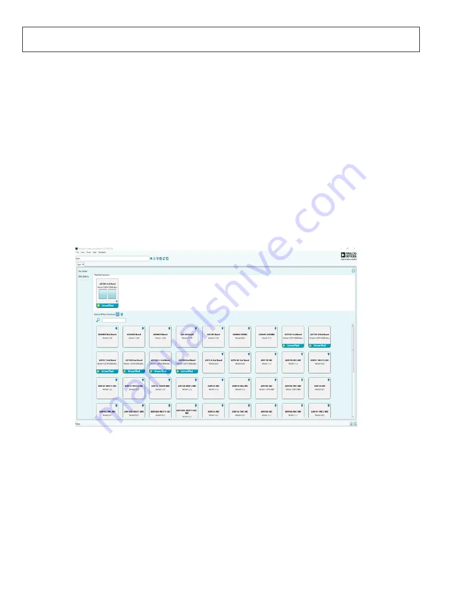
, which opens the window
shown in Figure 12.
2.
If the EVAL-AD7386FMCZ evaluation board is not connected
to the USB port via the
when the software
is launched, the
AD7386 Eval Board
icon does not show up
in the
Attached Hardware
section. Connect the EVAL-
AD7386FMCZ and
to the USB port of
the PC and wait a few seconds. Then, follow the instructions.
Double-click the
AD7386 Eval Board
icon to view the
board view (see Figure 13).
3.
Double-click the
AD7386
chip icon to open the chip view
window (see Figure 14).
4.
Click
Software Defaults
and then click
Apply Changes.
DESCRIPTION OF CHIP VIEW
After completing the steps in the Software Installation Procedures
section and the Evaluation Board Setup Procedures section, set
up the system for data capture as follows:
1.
Block icons that are dark blue are programmable blocks.
Click a dark blue block icon to open a configurable pop-up
window that allows customization for data capture, as
shown in the
Over Sampling
block in Figure 16.
2.
Type the value of the reference voltage in the
Reference
Voltage
box when
External Reference
is selected
(
click the
REF
block in Figure 15 to access this option). The default
value for the external reference is set to 3.3 V and 2.5 V for
the internal reference.
2
1
193-
012
Figure 12.
Evaluation Software Main Window


