background image

EVAL AD5933-U1 

Preliminary Technical Data


Rev. PrA | Page 6 of 16 

GETTING STARTED 

SETUP SEQUENCE SUMMARY  

This installation was done using the Windows XP operating 
system. The installation consists of the following steps, which 
are described in detail in the sections that follow. 

1.


Install the graphical user interface software. Do not 
connect the USB cable from the AD5933 evaluation board 
to the computer USB hub at this stage. See Step 1—Install 
the Software. 

2.


Connect the USB port from the computer to the evaluation 
board, and run the USB installation wizard. See Step 2—
Connect the USB Cable. 

3.


Ensure that the appropriate links are made through out the 
evaluation board. Power up the evaluation board. See Step 
3—Verify the Links and Power Up. 

4.


Use the evaluation board software to run the sweep 
function. See Step 4—Perform a Frequency Sweep. 
 

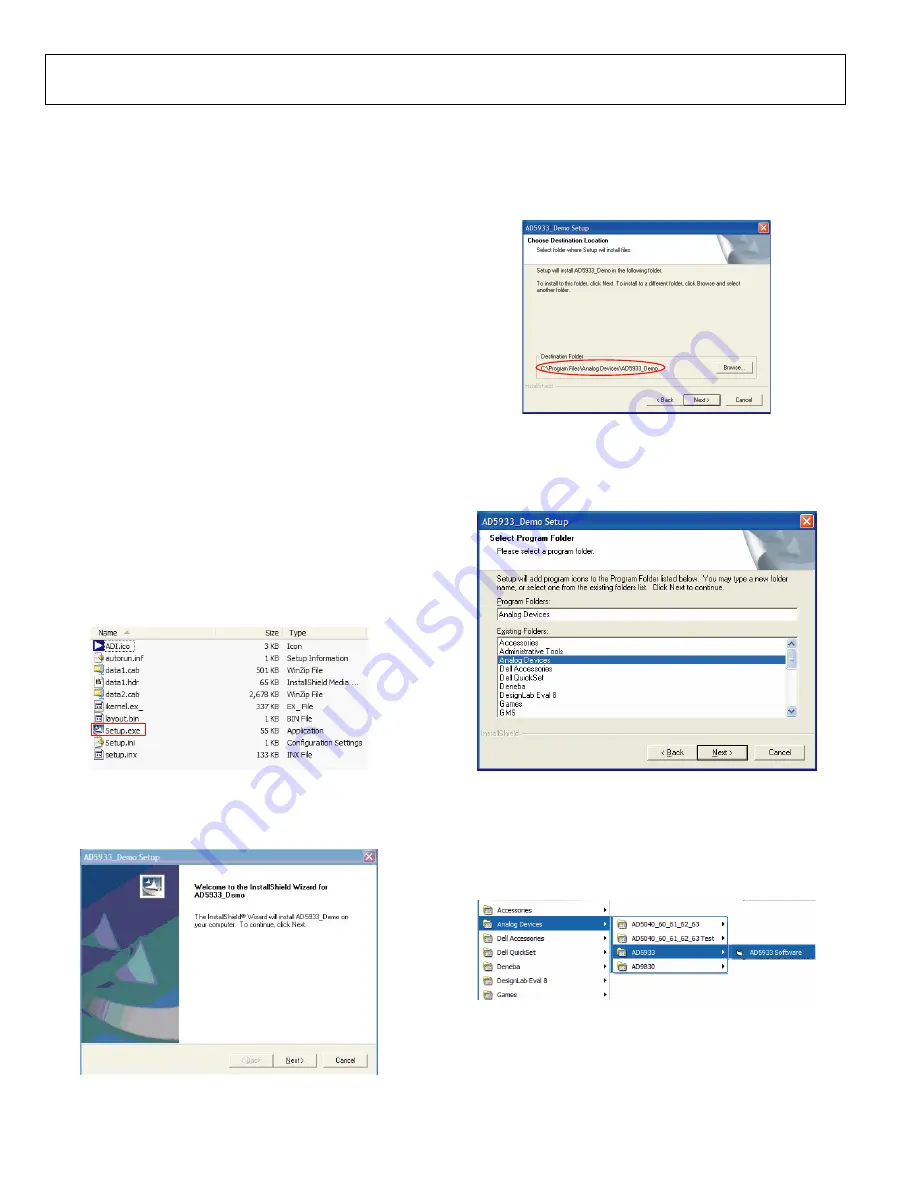
STEP 1—INSTALL THE SOFTWARE 

Place the CD accompanying the evaluation board into the CD 
drive of the user computer and open 

My Computer

. Double-

click the disk drive icon. Go to 

AD5933 Installation

 > 

Setup.exe 

(Figure 3).  

05435-002


Figure 3. 

Double-click 

Setup.exe

 and install the software on the hard 

drive of your computer through the installation wizard (Figure 4).  

05435-003


Figure 4. 

It is recommended to install the software in the default 
destination folder path, 

c\Program Files\Analog 

Devices\AD5933 Demo

 (Figure 5). 

05435-004


Figure 5. 

Choose 

Analog Devices

 (Figure 6). If the Analog Devices 

folder does not yet exist, create a folder called Analog Devices 
and add the program icon to this new folder.  

05435-005


Figure 6. 

After installing the software, remove the CD from the disk 
drive.  

Go to 

Start

 > 

All Programs

 > 

Analog Devices

 > 

AD5933 

AD5933 Software

 (Figure 7).  

05435-006


Figure 7. 

Содержание EVAL AD5933-U1

Страница 1: ...mbines an on board frequency generator with a 12 bit 1 MSPS ADC The frequency generator allows an unknown external impedance to be excited with a known frequency The response signal from the impedance...

Страница 2: ...uration and Function Descriptions 5 Getting Started 6 Setup Sequence Summary 6 Step 1 Install the Software 6 Step 2 Connect the USB Cable 7 Step 3 Verify the Links and Power Up The Evaluation Board 7...

Страница 3: ...AD5933 Analog Circuitry Input Supply AVDD REF is decoupled to the analog ground plane AGND J9 2 via standard 0 1 F and 10 F suppression capacitors J10 2 AGND Terminal Block Analog Ground Connection De...

Страница 4: ...an operational amplifier LK7 This link is inserted to connect the Tf2 OUT SMB connector to the inverting terminal of the transimpedance amplifier within the AD5933 This link is required to complete th...

Страница 5: ...edance amplifier Test impedance is connected between this pin and the VOUT pin 6 VOUT Output AC Excitation Signal Programmable frequency range 0 Hz to 50 kHz Test impedance is connected between this p...

Страница 6: ...aluation board software to run the sweep function See Step 4 Perform a Frequency Sweep STEP 1 INSTALL THE SOFTWARE Place the CD accompanying the evaluation board into the CD drive of the user computer...

Страница 7: ...not passed the Windows logo testing to verify compatibility with Windows XP This error appears because this is an evaluation setup installation and not meant to be used in a production environment Cli...

Страница 8: ...ace program is run it appears as shown in Figure 13 The figure shows the interface along with an impedance profile for a sweep across 15 pF ceramic capacitive impedance This section describes how to s...

Страница 9: ...this example choose capacitor only to measure the impedance sweep across a capacitor For this example enter 0 the Resistor Value box and 15E 12in the Capacitor Value box To program the sweep condition...

Страница 10: ...the impedance of the network under analysis varies across the programmed frequency range To view how the relative phase across the network under analysis varies click relative phase vs frequency The...

Страница 11: ...e Device Manager Expand Other devices Figure 22 05435 017 1 EXPAND THIS DIRECTORY 2 RIGHT CLICK ON THIS DEVICE Figure 22 The computer has not recognized the USB device that is the AD5933 evaluation bo...

Страница 12: ...15 14 13 12 11 10 9 T1 T2 T5 T6 R2 50 LK7 OP97 U1 OUT 6 7 4 2 3 VIN TRIM VOUT GND U4 ADR425 C32 0 1 F C31 10 F 2 5 6 4 CLK2 LK6 LK2 LK3 LK4 LK5 C25 10 F C26 0 1 F C30 10 F C28 0 1 F C2 10 F C24 0 1 F...

Страница 13: ...OE PA3 WU2 PA4 FIFOADR0 PA5 FIFOADR1 PA6 PKTEND PA7 FLO SLCS RDY0 SLRD RDY1 SLWR IFCLK RSVD AGND GND GND GND GND GND GND GND AVCC VCC VCC VCC VCC VCC VCC VCC VCC WP SCL SDA U2 24LC64 C22 0 1 F 3 3V 8...

Страница 14: ...8 ADP3300 3 3 8 7 1 IN1 2 6 3 SD GND OUT2 ERROR NR IN2 5 1 4 C16 0 1 F T1 T2 T3 T4 C15 0 1 F C14 10 F 3 3V D4 3 3V R24 1k Figure 26 05435 027 C12 10 F C11 0 1 F DVDD_5V DGND J2 2 J2 1 C35 10 F C36 0 1...

Страница 15: ...ve device Electrostatic charges as high as 4000 V readily accumulate on the human body and test equipment and can discharge without detection Although this product features proprietary ESD protection...

Страница 16: ...5933 U1 Preliminary Technical Data Rev PrA Page 16 of 16 NOTES 2005 Analog Devices Inc All rights reserved Trademarks and registered trademarks are the property of their respective owners EB05435 0 3...

Отзывы: