Evaluation Board
User Guide
Rev. A | Page 5 of 14
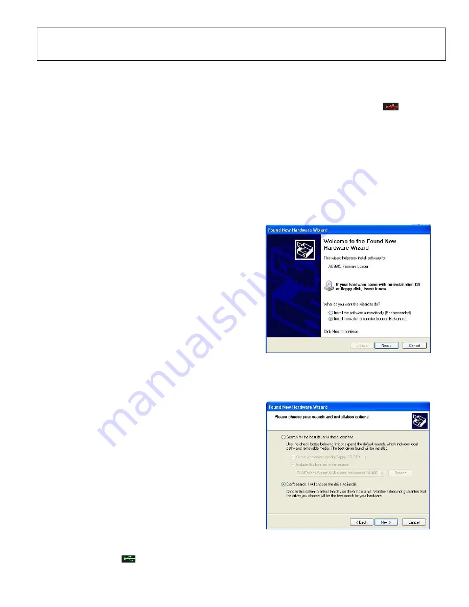
EVALUATION BOARD SOFTWARE
SOFTWARE INSTALLATION
Do not connect the evaluation board until the software
installation is complete. An installation CD is provided with
each evaluation board.
NOTE: The software requires a Windows XP operating
system
.
Follow these steps to install the evaluation board software:
1. Log into your computer system with administrative
privileges.
2. Insert the evaluation board software CD into your CD-ROM
drive.
3. For computers that do not have
.NET Framework 3.5
installed,
use the
“AD9915_Setup_v1.0.4002.29083_Full
”
executable file to install the prerequisite and the evaluation
board software. For computers that have it, the installation can
be made by using “
AD9915_Setup_v1.0.4002.29083
”.
4. The next step would be the driver installation.
DEVICE DRIVER INSTALLATION
1. Power up the evaluation board.
2. Connect the evaluation board to the computer via the USB
port using a USB cable. Then, a green LED light
(D200)
would
illuminate to indicate USB connection.
3. When the USB cable is connected, the
Found New
Hardware Wizard
appears. Click
Next
to continue the
installation of a new driver.
4. Click
Continue Anyway
when the
Hardware Installation
Warning
window appears.
5. Click
Finish
in the
Found New Hardware Wizard
when
installation is complete.
6. When a second
Found New Hardware Wizard
dialog box
appears, just repeat steps 3-5.
STARTING THE SOFTWARE
Before you start the software, make sure that the AD9915
evaluation board is powered up and connected to the PC, and
the LED D200 (USB status) is on. Refer to Power Supply
Connections in this user guide for correct settings.
To start the AD9915 evaluation software, follow these steps:
1.
Click the
Start
button (located at the bottom left corner of
your desktop).
2.
Select
All Programs
>
Analog Devices
>
AD9915
Evaluation Software
.
3.
Click
AD9915 Evaluation Software
to start the software.
A
successful connection
of the software to the board is
indicated by this green icon
, which can be found at the
bottom right corner of the window. An
unsuccessful
connection
is indicated by this flashing red
icon.
Most installation errors can be resolved by checking jumper
settings, making sure that the evaluation board is powered up
correctly, and inspecting the USB port and cable connections.
When all power, USB port/cable connections, and jumper
settings are correct, an error may still appear if the clock input
is not properly configured. Check to make sure that the clock
input source is connected and properly configured.
Another reason is due to conflicting device driver. This can be
fixed by updating the driver. You can do this by plugging the
USB connector into another USB port. The computer would
then inform you to install a device driver and a window would
come into display.
Figure 3. Found New Hardware Wizard Dialog Box.
Choose the selection indicated by Figure 3.
Figure 4. Choose Driver to Install
Again, choose the indicated selection as in Figure 4 then click
Next
.


