Evaluation Board User Guide
UG-169
Rev. 0 | Page 3 of 12
EVALUATION BOARD HARDWARE
The following instructions are for setting up the physical
connections to the AD9523 evaluation board.
SETTING UP JUMPER CONNECTIONS
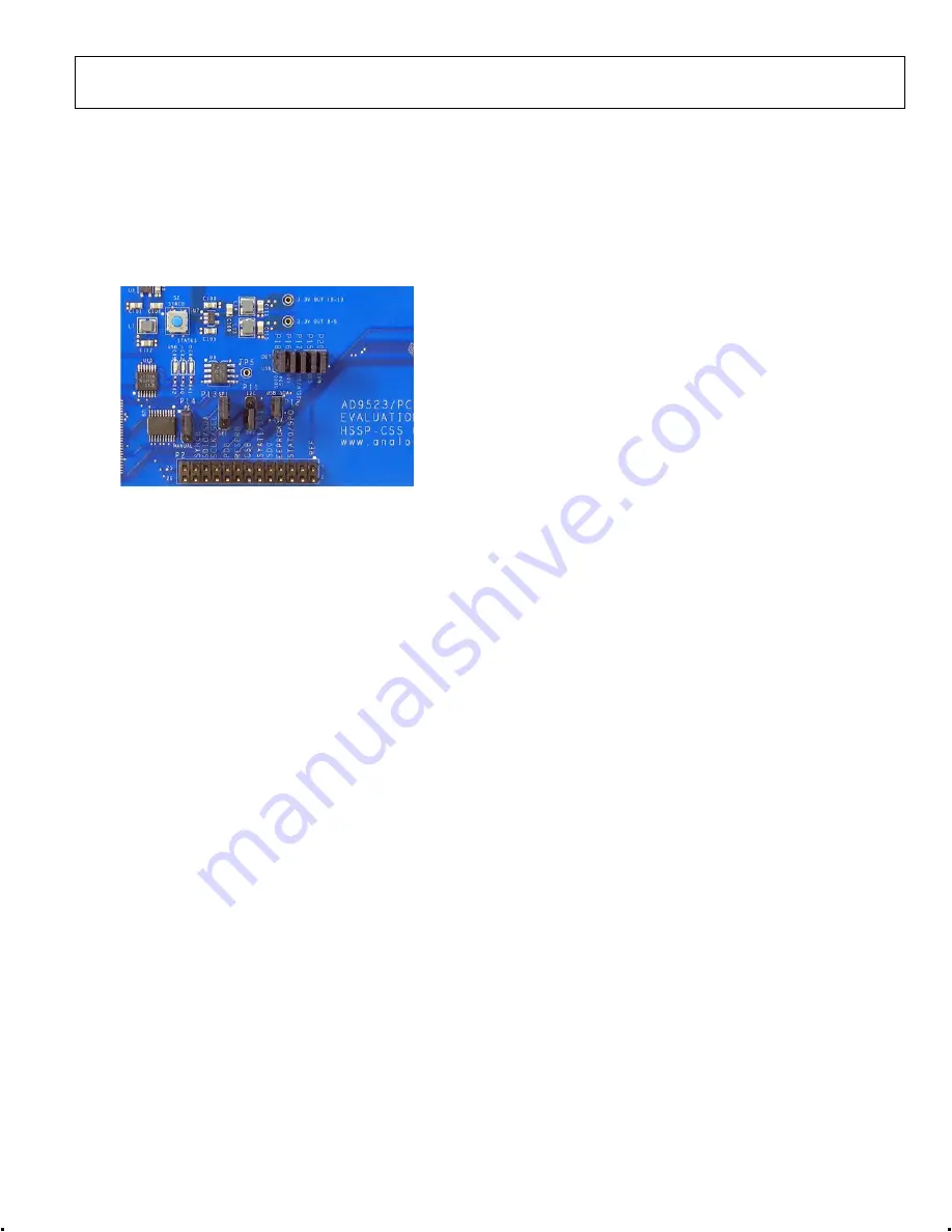
The evaluation board is configured for proper PC control and
operation. If the jumpers are inadvertently moved, use Figure 2
and Figure 3 to reconfigure the board.
0
91
71
-0
02
Figure 2. USB and SPI Jumper Connections
SETTING UP THE POWER AND PC CONNECTIONS
Set up the power and PC connections as follows:
1.
Install the AD9523 evaluation software before connecting
the evaluation board to the PC for the first time (see the
Installing the Software section). Administrative privileges
are required for installation.
2.
Connect the 6 V wall adapter to Connector P7 of the
evaluation board.
3.
Connect the USB cables to the evaluation board and the
computer.
4.
Found New Hardware Wizard
automatically appears
when the evaluation board is connected. Select
Install the
software automatically
and then click
Next
.
The
Found New Hardware Wizard
may appear twice, and
a system restart may be required.
Refer to the Evaluation Board Software Setup section for details
on running the AD9523 evaluation board software.
SETTING UP THE SIGNAL CONNECTIONS
After setting up the power and PC connections, use the
following procedure to set up the signal connections:
1.
Connect a signal generator to REF A SMA Connector J9.
By default, the reference inputs on this evaluation board
are ac-coupled and terminated 50 Ω to ground. An
amplitude setting of 6 dBm is sufficient.
2.
Connect an oscilloscope, spectrum analyzer, or other lab
equipment to any of the OUTx SMA connectors on the
right side of the board. The output connectors are single-
ended outputs of a differential pair. A 50 Ω termination
should be placed on all unused differential output pair.
BYPASSING THE 6 V WALL SOCKET POWER
SUPPLY
The evaluation board contains a dc-to-dc converter to step
down the 6 V to 2.2 V and 4 V. Linear regulators are then used
to further regulate the 2.2 V to 1.8 V supply domain and the 4 V
to the 3.3 V supply domain. The evaluation board can be config-
ured to bypass the dc-to-dc converter and linear regulators or
the dc-to-dc converter only. This is useful for measuring the
AD9523 power consumption. Refer to the evaluation board
schematics provided on the CD in the evaluation board kit (also
available at
) for further details.
Bypass the 6 V power supply (dc-to-dc converter and linear
regulators) as follows:
1.
Note that it is very important to not have the 6 V supply
connected to the evaluation board while using external
supplies. To be safe, remove the inductors from each linear
regulator output (L4 to L15).
2.
Connect a bench power supply to each of the supply pins
on Header TP3 through Header TP15. If the inductors
were not removed in Step 1, then some of the supply pins
are connected together on the evaluation board and
damage to the external supply and/or evaluation board
may occur.
Bypass the 6 V power supply (dc-to-dc converter only) as
follows:
1.
Remove L1, L2, L3, R39, R41, R40, and R42.
2.
Connect a 2.2 V bench supply to Connector P19. Connect
a 4 V bench supply to the L1 pad.


