background image

August 2012

L010440

10

Determine Output Current

The output current used for motor when microstepping is determined differently from that of a 

full/half step unipolar driver.  In the MBC25SI1TB, a sine/cosine output function is used in rotat-

ing the motor.  The output current for a given motor is determined by the motors current rating 

and the wiring configuration of the motor.  There is a current adjustment potentiometer used to 

set the output current of the MBC25SI1TB.  This sets the peak output current of the sine/cosine 

waves.  The specified motor current (which is the unipolar value) is multiplied by a factor of 1.0, 

1.4, or 2.0 depending on the motor configuration (series, half-coil, or parallel).

Step Motor Configurations

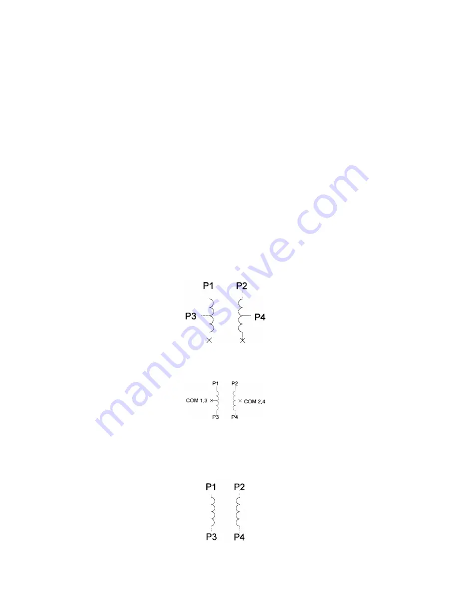
Step motors can be configured as 4, 6, or 8 leads.  Each configuration requires different currents.  

Refer to the lead configurations and the procedures to determine their output current.

WARNING! 

Step motors will run hot even when configured correctly.  Damage may occur to the 

motor if a higher than specified current is used.  Most specified motor currents are maximum 

values.  Care should be taken to not exceed these ratings.

6 Lead Motors

When configuring a 6 lead motor in a 

half-coil configuration 

(connected from one end of the coil 

to the center tap), multiply the specified per phase (or unipolar) current rating by 1.4 to determine 

the current setting potentiometer value.  This configuration will provide more torque at higher 

speeds when compared to the series configuration.

When configuring the motor in a 

series configuration 

(connected from end to end with the cen-

ter tap floating) use the specified per phase (or unipolar) current rating to determine the current 

setting potentiometer value.

4 Lead Motors

Multiply the specified 

series 

motor current by 1.4 to determine the current adjustment potenti-

ometer value.  4 lead motors are usually rated with their appropriate series current, as opposed 

to the

 Phase Current

, which is the rating for 6 and 8 lead motors.

July 2018

Содержание MBC25SI1TB

Страница 1: ...TB Programmable Simple Indexer Driver User s Guide 4985 E Landon Drive Anaheim CA 92807 e mail info anaheimautomation com 714 992 6990 fax 714 992 0471 website www anaheimautomation com A N A H E I M...

Страница 2: ...the Output Current 9 Potentiometer Settings 9 Reducing Output Current 9 Determining Output Current 10 Step Motor Configurations 10 6 Lead Motors 10 4 Lead Motors 10 8 Lead Motors 11 Connecting the St...

Страница 3: ...er with 4 Motion Profiles Pulses From 1Hz to 50kHz Directional Soft and Hard Limit Switch Inputs Clock Output for Daisy Chaining Busy Output Motor On Off Input and Automatic Current Reduction Short Ci...

Страница 4: ...op Soft Limit Activated During Index A A Profile input is activated Ramps up to max speed B No limit is active Max speed is reached keeps running at max speed C No limit is active Internal counter sig...

Страница 5: ...ge direction while using the software change the direction option there When two motors are used the second motor will move in the opposite direction by default On Off When this input is not active th...

Страница 6: ...2 B 4 Phase 4 B Connector P2 Pin Description 1 Power Supply Ground 0VDC 2 Power Supply Input 12VDC 35VDC 3 Motor On Off 4 Direction In 5 Profile 4 6 Profile 3 7 Profile 2 8 Profile 1 9 Ground 0VDC Con...

Страница 7: ...Start Active Direction Input P2 Pin 4 CW Inactive CWW Active On Off Input P2 Pin 3 On Inactive Off Active Busy Output Pin 11 Open Drain type Output 75mA Sink 40VDC Stand Off Clock Output Pin 12 Open...

Страница 8: ...August 2012 L010440 8 Dimensions Wiring Diagrams July 2018...

Страница 9: ...e driver This relationship between the output current and the potentiometer setting is as follows Potentiometer Settings Reducing Output Current Reducing the output current is accomplished automatical...

Страница 10: ...current WARNING Step motors will run hot even when configured correctly Damage may occur to the motor if a higher than specified current is used Most specified motor currents are maximum values Care...

Страница 11: ...to accept one motor For wiring of the motor refer to the pages containing the connector descriptions and hookups diagrams Note The physical direction of the motor with respect to the direction input w...

Страница 12: ...er of steps per second This speed must always be less than the max speed The different base profiles are stored in EEprom for standalone use Range 1 to 5000 Max Speed The max speed is the top speed th...

Страница 13: ...Run 3 Enter D setup and click OK use the appropriate drive letter i e D or E Windows 95 98 NT ME 2000 XP Installation Option 1 1 Insert the CD into the drive 2 From the Program Manager select Start Ru...

Страница 14: ...se by other devices Communication Settings COM port Selection Ports 1 2 3 4 5 6 or 7 Exit Exit the SMPG SMSI Software Connect Establish communications with the controller The Unit is Connected The Uni...

Страница 15: ...r parameter to the indexer steps Begin Motion Motor will ramp up to maximum speed and keep moving until a limit switch is triggered or the index is complete Soft Limit Motor will ramp down to base spe...

Страница 16: ...r the command the pulse generator will return a SMSI10 the current version number Note In direct talk mode each command is followed by a carriage return The unit communicates in half duplex mode there...

Страница 17: ...s the motion profile number 1 thru 4 Sample A1_10000 Accel of profile 1 equals 10000 Description This command sets the acceleration profile which can be an integer value between 100 and 9 999 999 Thes...

Страница 18: ...tion commands H Hard Limit or Stop Motion Format H Description This command will stop all motion It can only be used when pulses are running M Max Speed Format M _ value where is the motion profile nu...

Страница 19: ...a 0 is sent back then the driver is not in reduced current mode D If a 1 is sent back then the pulse generator will ramp down to stop when the Run Stop input is released If a 0 is sent back then the p...

Страница 20: ...priate power supply 2 Check for any blown fuses in line with the unit 3 If problems still exist contact Anaheim Automation at 714 992 6990 Problem The indexer has a fault condition Possible Solutions...

Страница 21: ...ters are invalid for the command that was sent 4 Command Error A bad command was sent to the pulse generator Please check to see that the command being sent is valid or that the pulse generator is not...

Страница 22: ...aheim Automation products in life support applications assumes all risks of such use and indemnifies Anaheim Automation against all damages LIMITED WARRANTY AllAnaheimAutomation products are warranted...

Отзывы: