

For full warranty information, refer to the AMX AutoPatch Instruction Manual(s) associated with your Product(s).
5/08
©2008 AMX. All rights reserved. AMX and the AMX logo are registered trademarks of AMX.
AMX reserves the right to alter specifications without notice at any time.
3000 RESEARCH DRIVE, RICHARDSON, TX 75082 • 800.222.0193 • fax 469.624.7153 • technical support 800.932.6993 • www.amx.com
93-46-861
REV:
B
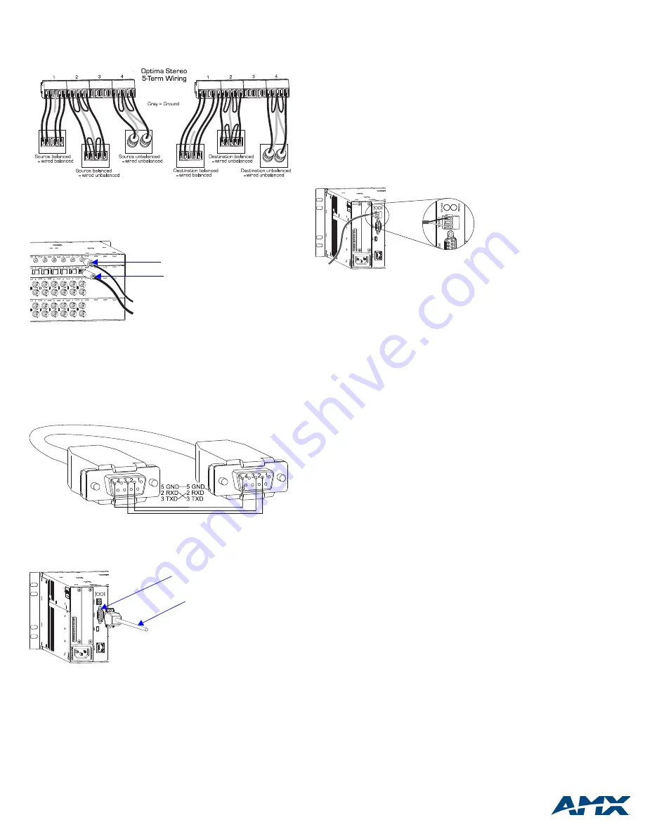
Note:
When using shielded twisted-pair wire, connect the shield (ground) at one end
only (recommend receiving end) to minimize low frequency noise (see FIG. 7).
Source and destination devices require either balanced or unbalanced connections.
More than one of the options shown in FIG. 7 can be used in the same system.
Digital Audio Boards – S/PDIF & TosLink
S/PDIF connectors are coaxial, and TosLink connectors are optical (remove the
protective caps from the TosLink jacks).
Establishing Serial Control (if applicable)
The Optima can be controlled by attaching an external control device/system to the
serial port or to the XNNet Link Connector (Link A), which uses AutoPatch XNNet
protocol for AMX AutoPatch devices.
Serial Control (PCs,
NetLinx
®
, & third-party controllers)
Use the pinout in FIG. 9 when connecting a PC to the Optima serial port.
To establish external serial control:
1.
Plug the null modem cable into the RS-232 (DB-9) serial port on the enclosure
(see FIG. 10).
2.
Plug the other end of cable into the serial port on the serial controller/device.
3.
Open serial communication software and set port settings to match the Optima
default settings (baud = 9600, data bits = 8, stop bit = 1, parity and
flow control = none).
XNNet Control (AMX AutoPatch remote control panels, SBCs, etc.)
XNNet connectors (Link A) are on the CPU for 3 RU enclosures and are available on
an expansion board for 2 RU enclosures.
Communication Cable Requirements:
•
Two-conductor, 20 AWG, 7/28 strand cable with a drain wire or shield, such as
Alpha 2412C (customer supplied)
•
Maximum cable length: 1,000 ft. (304.8 m) total, including linked devices
On large control networks, termination may be required on the last linked device;
for termination information, see the device’s documentation.
To establish external XNNet control:
1.
Attach XNNet link cable to XNNet device according to the device’s instructions.
2.
Unplug the Link A (XNNet) connector on the Optima and loosen the screws.
3.
Insert XNNet link cable wires according to FIG. 11 (either wire can be inserted
in either outside slot).
4.
Tighten screws and plug in the connector.
Applying Power & Control Startup
Important:
We recommend attaching all power cords to a surge protector and/or an
AC line conditioner.
To apply power:
1.
Attach power cord(s) and plug into power source (turn on power source if
necessary). The Power Indicator on the front of the enclosure illuminates.
2.
Apply power to any external devices (remote control panels, etc.) and then to
the source and destination devices.
Startup Control Options
•
Control Panel
(front or remote)
– the LCD on the panel illuminates and
displays the menu screen.
•
NetLinx
®
Compatible Devices
– AMX AutoPatch distribution matrices are
NetLinx
®
compatible. For specific control programming information, please
contact your AMX representative.
•
APControl 3.0
– install and open the program. Follow the setup wizard, which
will discover the system’s configuration information and open the APControl
Launchbar.
•
APWeb
– for information about the APWeb board, see the instruction manual.
For APWeb Module information, see the APWeb Module Quick Start Guide.
•
BCS Commands
(HyperTerminal) – when power is applied, a short splash
screen appears.
Completing the Installation
To complete the installation:
1.
Execute a test switch that routes Input 1 to Output 2.
Control Panel
(front or remote) – see the control panel’s Quick Start Guide.
NetLinx
®
or Duet Compatible Devices
–
see the specific controller device
documentation.
APControl 3.0
– Follow the setup wizard, which will discover the system’s
configuration information and open the APControl Launchbar. From the
Launchbar menu, to disconnect the default switch; deselect all active cross-
points.
From the Launchbar menu, to execute a test switch, select Views/CrossBar
and click on the crosspoint for Input 1 / Output 2.
APWeb
– For instructions on executing switches, see the APWeb (Interface)
documentation. Remember to disconnect the default switch before executing a
test switch.
BCS Commands
(HyperTerminal)
– when power is applied, a short splash
screen appears. To execute a test switch: enter
CL#I1O2T
(#
= a level
on the
AutoPatch Connector Guide
) into the terminal emulation program
(routes Input 1 to Output 2). When
CL#I1O2T
appears, the switch is
successful.
2.
Attach the remaining source and destination devices according to the
AutoPatch Connector Guide
.
Additional Information Covered in Optima Instruction Manual
See the Instruction Manual on the CD or at
www.amx.com
for the following:
• Setting up and executing global or local presets
• Customizing channel names
FIG. 7
Options for source-to-Optima-to-destination 5-Term wiring
FIG. 8
Attach S/PDIF & TosLink connectors
FIG. 9
RS-232 cable pin diagram
FIG. 10
Attach null modem serial cable
Inputs
Outputs
C
C
C
C
Y
Y
Y
Y
Y
Y
C
C
C
C
C
C
Y
Y
Y
Y
Y
Y
C
C
S/PDIF connector
TosLink connector
Null modem serial cable
Serial port
FIG. 11
Insert wires into XNNet connector (Link A)


