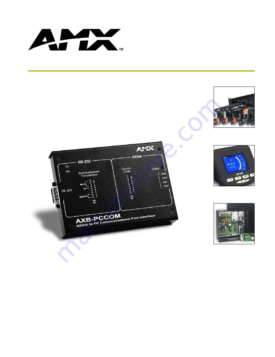
manualshive.com logo in svg
background image

instruction manual

AXlink Bus Controllers

AXB-PCCOM

AXlink to PC Communications Port 
Interface

Содержание AXB-PCCOM

Страница 1: ...instruction manual AXlink Bus Controllers AXB PCCOM AXlink to PC Communications Port Interface ...

Страница 2: ... liability applies whether damages are sought or a claim is made under this warranty or as a tort claim including negligence and strict product liability a contract claim or any other claim This limitation of liability cannot be waived or amended by any person This limitation of liability will be effective even if AMX Corporation or an authorized representative of AMX Corporation has been advised ...

Страница 3: ...P Switches 2 Communication Parameters 2 Device Code 3 Connectors 4 Preparing connecting captive wires 4 Using the AXlink connector for data and power 4 Using the RS 232 DB 9 connector control or data 5 Programming 7 Requests 7 Request Commands 7 Send_Commands 9 Response Commands 10 Response Mask 11 Axcess Master Mode 11 ...

Страница 4: ...ii AXB PCCOM Communications Port Interface Table of Contents ...

Страница 5: ... AXB PCCOM protocols to control AXCESS systems Can be located up to 3 000 feet from AXCENT AXCENT2 or Axcess card cage This overcomes the RS 232 distance limitation of 50 feet or less Does not require special Axcess programming to work on AXlink In programming treat AXB PCCOM as a standard Axcess panel FIG 1 AXB PCCOM top view PARAMETERS COMMUNICATION 6 5 4 8 7 2 1 3 RS 232 ON DEVICES HS BAUD RX T...

Страница 6: ...vice 64 Max Length of data packets from device 64 Weight 8 60 oz 243 80 g Panel Components RS 232 connector A DB 9 RS 232 connector used for communication with the PC for AMX programming tools such as Axcess and IRLIB TX LED Red Blinks to indicate that the AXB PCCOM is transmitting data RX LED Red Blinks to indicate the AXB PCCOM is receiving data The RX LED blinks even if the data is incorrect Co...

Страница 7: ...switch setting example Communications Parameters DIP switch settings Switch 1 Switch 2 Switch 3 and 4 Switch 5 Switch 6 Switch 7 Switch 8 Off Off Off Off Off Off Two AXlink devices Reserved Handshaking disabled 300 Baud On Off On On Off Off Two AXlink devices Handshaking disabled 600 Baud Off On Off On Off Three AXlink devices 1 200 Baud On On On On Off Four AXlink devices 2 400 Baud Off Off On 4 ...

Страница 8: ...ibed in this section 3 Do not tighten the screws excessively doing so may strip the threads and damage the connector Using the AXlink connector for data and power To use the AXlink 4 pin connector for data communication and for power supply the incoming PWR and GND cable from the control system must be connected to the AXlink cable connector going to the control system The AXlink connector is loca...

Страница 9: ... RS 232 connector pinouts and signal definitions FIG 6 RS 232 DB 9 connector location on AXB PCCOM DB 9 RS 232 Connector Pinouts Pin Signal Function 1 N A Not used 2 RXD Receive data 3 TXD Transmit data 4 DTR Data terminal ready not used 5 GND Signal ground 6 N A Not used 7 RTS Request to send not used 8 CTS Clear to send not used 9 N A Not used RS 232 connector 9 8 7 6 5 4 3 2 1 9 8 7 6 Female on...

Страница 10: ...Product Information 6 AXB PCCOM Communications Port Interface ...

Страница 11: ...le 0 corresponds to 1 1 corresponds to 2 and so on CHECKSUM the sum of all bytes mod 256 For the equation X mod Y N X is divided by Y with the remainder being N All examples are for an AXB PCCOM set as AXlink device number 128 configured for four devices Request Commands The following table lists the request commands sent to the AXB PCCOM Requests sent to the AXB PCCOM Command Packet Structure and...

Страница 12: ...Levels Syntax 12 DEVICE CHECKSUM Example 12 2 56 Request the AXB PCCOM to send level status for all levels on device 2 AXlink device 129 The AXB PCCOM responds with a CHANGE LEVEL string for each level for device 2 Send All On Channels Syntax 11 DEVICE CHECKSUM Example 11 1 54 Request the AXB PCCOM to send all on channels for device 1 AXlink device 129 The AXB PCCOM responds with a channel status ...

Страница 13: ... the AXB PCCOM to send CHANNEL STATUS and RECEIVE STRING strings Refer to the Response Mask section on page 11 for more information AXB PCCOM Send_Commands Command Packet Structure and Example RXON Enables strings to be sent to master RXOFF Disables strings to be sent to master LEVON Enables levels to be sent to master LEVOFF Disables levels to be sent to master PASS ON AXB PCCOM is put into PASS ...

Страница 14: ...ed When AXlink goes back on line it sends BUS STATUS again 6 0 44 The bus is Off line Change Level Syntax 2 DEVICE LEVEL NO LEVEL CHECKSUM Example 2 1 2 132 175 Level 2 on device 1 AXlink device 129 is 132 Channel Status Syntax 1 DEVICE CHANNEL STATUS CHECKSUM Example 1 0 255 1 39 Channel 255 on device 0 AXlink device 128 is On 1 3 100 0 142 Channel 100 on device 3 AXlink device 131 is Off Device ...

Страница 15: ...EVICE BYTES STRING CHECKSUM Example 3 0 9 AXB PCCOM 172 AXCESS sent the string AXB PCCOM to device 0 AXlink device 128 Response Mask for the AXB PCCOM Byte Bit Data Controlled Default First byte mask 1 7 msb Receive String 1 6 Receive Channel 1 5 Channel Change 1 4 Level Change 1 3 Bus LED 0 2 Reserved for Future use 0 1 Reserved for Future use 0 0 lsb Reserved for Future use 0 Second byte mask 2 ...

Страница 16: ...A BELGIUM BRAZIL CANADA CHINA ENGLAND FRANCE GERMANY GREECE HONG KONG INDIA INDONESIA ITALY JAPAN LEBANON MALAYSIA MEXICO NETHERLANDS NEW ZEALAND PHILIPPINES PORTUGAL RUSSIA SINGAPORE SPAIN SWITZERLAND THAILAND TURKEY USA ATLANTA BOSTON CHICAGO CLEVELAND DALLAS DENVER INDIANAPOLIS LOS ANGELES MINNEAPOLIS PHILADELPHIA PHOENIX PORTLAND SPOKANE TAMPA 3000 RESEARCH DRIVE RICHARDSON TX 75082 USA 800 22...

Отзывы: