AMS OSRAM NanEye Скачать руководство пользователя страница 10


Document Feedback 

NanEye 


Hardware Description 


Eval Kit Manual 

• PUBLIC 


UG001036 

• v3-00 • 2022-May-31 

43


│ 9 


Please take the following steps to perform the correct connection: 

1. 

Please ensure that the NanEye Viewer software has been correctly installed, refer to section 
3.2.  

2. 

Plug the USB3 type A cable to the Fiber Optic Box and the PC. 

3. 

Plug in the 12 V DC power adapter and wait for the Fiber Box to power up. 

4. 

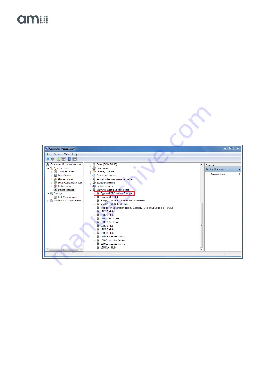
Wait for it to be automatically recognized. Please check on the 

Device Manager

 if your device 

is recognized as 

Cypress FX3 USB StreamerExample Device

 as shown in Figure 8.  

5. 

Connect the sensor to the respective port and wait for the green LED to be blinking. 

6. 

The NanEye Viewer can be started choosing the 

Camera

Board

 and 

Viewer,

 following the 

suitable combination available on Figure 31. If the board is not recognised correctly please 
check next sections Installing FX3 Driver Manually and How to Debug Fiber Optic Box.  

Figure 8: 
Fiber Optic Box Device Connection 


Installing FX3 Driver Manually 

If the driver is not correctly installed after installing NanEye Viewer, please go to: 

● 

Program Files (x86)\ams OSRAM\NanEye Viewer vx.x.x.x\driver\FX3_Driver


Then, according to the operating system, run the respective Drive Package Installer (

dpinst_x86/x64

). 


Содержание OSRAM NanEye

Страница 1: ...Product Document Published by ams OSRAM Group ...

Страница 2: ...User Guide UG001036 NanEye Evaluation Kits Fiber Optic Box 2 0 and NanoUSB2 2 v3 00 2022 May 31 ...

Страница 3: ...ction 3 1 1 Ordering Information 3 2 Hardware Description 4 2 1 Fiber Optic Box 2 0 4 2 2 NanoUSB2 2 13 3 NanEye Viewer Software 20 3 1 General Description 20 3 2 Software Installation 20 3 3 Start the Application 23 3 4 Common Issues 38 4 Schematics and Source Code 41 5 Revision Information 42 6 Legal Information 43 ...

Страница 4: ...e sensor in the frame brake The exposure time dark level analog gain and frame rate can be programmed over the serial configuration interface The Fiber Optic Box and NanoUSB2 evaluation kits are able to communicate with the NanEye sensors The NanEye Viewer software enables the user to send the sensor register values as well as grab the RAW images to store or add image processing Additional feature...

Страница 5: ...hich in this mode no additional PC or image processing is required The USB3 interface allows the connection to the NanEye Viewer running on a PC to get access to the sensor s raw images and control settings The main body of the demo kit measures only 17 cm x 17 cm x 5 6 cm and provides all necessary video processing and display driving plus the adjustable illumination Figure 1 Fiber Optic Box 2 0 ...

Страница 6: ...on and enhancements Figure 3 Fiber Optic Box 2 0 Pinout Description Front Side Rear Side JST Connector HDMI Output 2 x NanEye2D M XS 1080P60 to display NanEye 1 x Current source up to 22 7 mA channel 1 No additional PC needed Rotary Switch USB3 0 Light mode and intensity control Display NanEye channel 1 2 with NanEye Viewer software Adjust light intensity of distal LED ring Adjust image processing...

Страница 7: ...anEye module to the box 2 Then connect the box to the monitor using a HDMI cable 3 Plug in the 12 V DC power adapter and wait for the Fiber Optic Box to power up Fiber Optic Box Operation Dual Color Status LED Constant Green Status ok no sensor connected test pattern output via HDMI Blinking Green Sensor data transmission sensor is working successfully Blinking Amber pulse 1 second at least one er...

Страница 8: ...s for previous versions of the FOB 2 NanEye2D version with LED ring is a discontinued product When entering the User Mode for White Balancing Keep Values no changes relative to the White Balance set previously This is for the case the White Balance menu is entered the but actually is not intended to modify the current settings Default Values sets the default values i e 1 0 for RGB in case of no il...

Страница 9: ...C UG001036 v3 00 2022 May 31 43 8 Figure 6 Fiber Optic Box Plug and Play Layout 2 1 3 Operation with PC Recommended Connection The following image shows the necessary equipment for a direct connection to a PC Figure 7 Fiber Optic Box NanEye Viewer Equipment Connection ...

Страница 10: ...FX3 USB StreamerExample Device as shown in Figure 8 5 Connect the sensor to the respective port and wait for the green LED to be blinking 6 The NanEye Viewer can be started choosing the Camera Board and Viewer following the suitable combination available on Figure 31 If the board is not recognised correctly please check next sections Installing FX3 Driver Manually and How to Debug Fiber Optic Box ...

Страница 11: ...iewer Fpga Files NanEye_USB3 When this task is completed the information is displayed as below This means that the FPGA is programming correctly Figure 9 Fiber Optic Box FPGA Configuration If the NanEye Viewer still does not open please reinstall the software Information If the issues are still not solved please contact the Technical Support team 2 1 4 Permanent Flash Programming From production t...

Страница 12: ...OpticBox_USB3 and in the Viewer section will show ProgramFlash independently of the Camera chosen Before initiating this process please make sure that the FOB is connected to both power supply and USB3 port Figure 10 Flash Programming NanEye Viewer Layout Information This process can be done with or without a HDMI screen connected However is recommended to use a monitor to easily follow and observ...

Страница 13: ... Figure 12 Programming File Upload Process Once the programming data is transferred to the EVK the NanEye Viewer will notify to disconnect the USB3 cable as shown below Click OK and the NanEye Viewer will close Simultaneously the same notification is shown on the monitor Also note that the FOB LED will be blinking with amber color and it will maintain this state until the end of the full programmi...

Страница 14: ...verification Finally the flash update is finished As the programming is done the LED becomes constant green Now the user can now power cycle the system to then observe the layout as in Figure 6 Figure 17 Flash Verification Figure 18 Programming Done Power Cycle 2 2 NanoUSB2 2 2 2 1 Out of the Box The NanoUSB2 demo kit is the ideal basis for customers that intent to develop a video processing engin...

Страница 15: ... FPGA Xilinx Spartan 3D Power supply Via USB 5 V Housing dimensions 5 8 cm x 3 7 cm x 1 4 cm Board dimensions 5 2 cm x 3 04 cm LED supply 12 bit DAC 50 mA max 16 V max Controlled FPGA register Attention The NanoUSB2 Demo Kit is intended solely for evaluation purposes has no EMI approval and is not advisable for medical use ams OSRAM therefore is not liable for any damage or harm resulting from its...

Страница 16: ...1036 v3 00 2022 May 31 43 15 Figure 20 NanoUSB2 Demo Kit Connection Material The NanEye2D sensor FlexPCB connector should be connected as shows in Figure 21 where the pcb tracks and epoxy are facing outwards the NanoUSB2 Figure 21 NanEye2D Sensor Placed On NanoUSB2 Connector ...

Страница 17: ...mini B connector to the NanoUSB2 and the end USB type A to the PC 4 Wait for it to be automatically recognized Please check on Device Manager if your device is recognized as Cesys USB Device NANOUSB as shown in Figure 22 Figure 22 NanoUSB2 Device Connection to PC Installing Cesys Drivers Manually If in Device Manager the NanoUSB2 2 is not recognized in Figure 22 and shows Cesys Device NANOUSB load...

Страница 18: ...or sensor Attention Please make sure that before running BoardTester exe the NanEye Viewer application is closed and or an API is not running After executing the program a window like Figure 23 should appear If the NanoUSB2 2 is well connected and identified in Device Manager Devices detected throws the value 1 Otherwise will show a 0 Figure 23 Board Tester Layout NanoUSB2 Detected The next step i...

Страница 19: ...t can be a sensor related issue Therefore in order to find the root cause please see below the possible situations such as NanEye2D connector may not be placed correctly check section Recommended Connection Check Figure 21 USB2 communication issue Power cycle the NanoUSB2 2 Try a different USB port cable or machine NanoUSB2 2 female connector may be damaged NanEye2D module may be damaged connector...

Страница 20: ...Eye Hardware Description Eval Kit Manual PUBLIC UG001036 v3 00 2022 May 31 43 19 Figure 25 Board Tester Layout Cannot Read Sensor Data Information If the issues are still not solved please contact the Technical Support team ...

Страница 21: ...ty to acquire black and white gain masks Possibility to apply the algorithm automatic exposure control Possibility to adjust white balance automatically Perform permanent flash programming via USB3 This software also contains some image processing algorithms Colour reconstruction Adjust colour saturation Gamma correction only for colour version Adjust brightness Contrast stretching 3 2 Software In...

Страница 22: ...edback NanEye NanEye Viewer Software Eval Kit Manual PUBLIC UG001036 v3 00 2022 May 31 43 21 Figure 26 NanEye Viewer Installer Language 3 Select the installation folder Figure 27 NanEye Viewer Installation Folder ...

Страница 23: ... Kit Manual PUBLIC UG001036 v3 00 2022 May 31 43 22 4 Select the media folder where correction masks and other files will be saved Figure 28 NanEye Viewer Media Folder Selection 5 Installs the drivers for all the boards Figure 29 NanEye Viewer Installing ...

Страница 24: ...suitable combination available on Figure 31 If the board is not recognised correctly please check sections 2 1 3 and 2 2 2 Figure 31 Sensor and Board Selection Camera Board Viewer Connector NanEye2D 1 NanoUSB2 NanEye Viewer Sensor 1 FiberOpticBox_USB3 NanEye Stereo Viewer 2 Sensor 1 Sensor 2 NanEyeXS NanEyeM 1 Please note that NanEye2D version with LED ring is a discontinued product 2 The stereo f...

Страница 25: ...resented in Figure 32 For the first time initiating the software please choose Load Default Figure 32 NanEye Viewer Initial Interface 3 3 2 Graphical User Interface Description Main Interface The NanEye Viewer interface is displayed as exemplified in Figure 33 The description of each NanEye Viewer interface section is shown below for NanoUSB2 Please note that the layout may change depending on sen...

Страница 26: ...ay 31 43 25 Figure 33 NanEye Viewer Main Interface 1 Frame Rate and Exposure Time 5 Image Processing 2 Display Image 3 Zoom 4 History 6 FPN Correction 7 Sensor FPGA Registers 8 Fast Menu Fast Menu Figure 34 NanEye Viewer Fast Menu Function of icons from left to right Play Stop Grabbing Images ...

Страница 27: ... The More Options Menu presents different features Load Save configurations of the NanEye Viewer Image Statistics Video Visualizer to play RAW videos and convert to AVI Recording Manager Log File in order to follow the different Viewer actions Technical Support webpage About section The pixel intensity can be analysed through the histogram by choosing Image Statistics from More Options menu ...

Страница 28: ...essage is displayed to choose Raw Images Processed Images or both Figure 37 To conclude the recording the user should hit the same record button The Recording Manager in Figure 35 shows detailed information about the recorded file Figure 37 Video Format Option Processed Video Saves in AVI format Recommendation Use VLC program to open it Raw Video Saves in awvideo format Saves raw 10 bit pixels Sav...

Страница 29: ...r ID To watch the raw video the user can use the Video Visualizer tool Figure 38 available in More Options menu This tool can also be used to export all the video frames or the current frame when the video is paused both PGM and PNG formats When converting to AVI the user must chose the target frame rate value it only accepts whole numbers between 1 and 100 which should be close to the actual sens...

Страница 30: ...sure Sensor integration time Has 250 different values between 0 darkest and 249 brightest Vrst_Pixel Pixel reset voltage Has four different values between 0 and 3 Is recommended to use default value as 1 or 0 Vref_CDS CDS stage reference voltage Has four different values between 0 and 3 Works as second programmable offset Should be lower than ADC Offset value to not clip in dark maintaining high d...

Страница 31: ...d shows the area in which the AEC retrieves the DN values to perform the algorithm On the bottom of the image there are four blue lines which represents the Gain each line a Gain step value where the top one represents the highest value and a yellow line Exposure value increasing from left to right Region of Interest These values represent the area rows and columns that the algorithm uses to check...

Страница 32: ...Figure 41 and Figure 42 presents an example of images where the target value is 250 DN and 395 DN respectively having the same Region of Interest Hysteresis and Step Size values presented in Figure 40 When AEC is deactivated the sensor gain and exposure values from the algorithm are maintained Figure 41 AEC with Gain 1 and Exposure 200 Figure 42 AEC with Gain 3 and Exposure 222 Attention Gain and ...

Страница 33: ...fer to NanEye_NanEyeStereo_AN000447 RegSen0 8 LSB of NanEye2D 16 bit register RegSen1 8 MSB of NanEye2D 16 bit register NanEyeXS M Sensor Control Figure 44 and Figure 45 shows respectively the NanEyeXS and NanEyeM default registers that can be changed by the user in the Manual Control tab The NanEyeM NanEyeXS sensor control layout is very similar to the NanEye2D differing on the register setting w...

Страница 34: ...te the Automatic sensor power cycling and then insert the value 1 into IdleMode register The inverse procedure will remove the sensor of the idle mode Please note that this feature is not available in the NanEye2D sensor Information The Automatic sensor power cycling option is a unique feature of the Fiber Optic Box evaluation kit and specifically developed to NanEyeM NanEyeXS once these sensors h...

Страница 35: ...an check with the histogram When finished a message is displayed Black Mask created successfully How to Create White Masks Choose the File name Use a homogeneous light to reach 90 of saturation in the center ROI of 50x50 pixels When finished a message is displayed White Mask created successfully The files are created with the extension awblc and awwlc for Black and White masks respectively To load...

Страница 36: ...ain options for the sensors Please note that the adjustment of pixel colors factor will depend on the ambient light therefore there is not a fixed standard adjustment for all situations The default value is 1 but it can vary between 0 5 and 2 Reset button resets all color gains to 1 default Figure 51 Color Pre Gain White Balancing How to do White Balancing Point the sensor to a white surface objec...

Страница 37: ...ge Figure 52 Color Reconstruction It is possible to tune the image saturation with a slider or through a color matrix for Red 1st column Green 2nd column and Blue 3rd column channels Color Adjustment Matrix The default value is 1 2 does not change the gain of each channel The sum of the three boxes values of each component is equal to 1 to not change the image overall brightness To saturate the Re...

Страница 38: ...es a nonlinear gain to the image Brightness Applies a linear gain to the image Sharpness Allow to clean the image Only available on Open CV algorithm RAW Image Disables the image processing to only get RAW images Only masks are used when applied Skip Frames Used when the machine cannot handle all the frames that the sensor is sending Increasing the slider allows to skip more frames IsDebug Observe...

Страница 39: ...x is powered and does not show on Device Manager Figure 8 please try a different USB3 cable shorter the better USB3 port Machine If the Fiber Optic Box is powered and does show in Device Manager Verify if the sensor is correctly connected to the respective port The green LED should be blinking if a sensor is connected Verify if Sensor Board and Viewer choices in NanEye Viewer initial layout are se...

Страница 40: ...icates that the communication between sensor and EVK may have problems Therefore Check the sensor cable wires condition and its connector soldering If the sensor wires on connector are loose if possible please solder it 1 Check NanEye2D Module Handling Manual NanEye_AN000493 If the wires are disconnected near the sensor head zone no repair is possible Check EVK connectors status visual inspection ...

Страница 41: ...sor Images with Only Light and Dark Levels May not write successfully the register values for offset and gain configuration Possible poor electrical contact from the camera to the readout board One of the sensor differential pairs has a bad contact Information If the issues are still not solved please contact Technical Support team ...

Страница 42: ... Schematics and Source Code Eval Kit Manual PUBLIC UG001036 v3 00 2022 May 31 43 41 4 Schematics and Source Code For more info regarding the Evaluation Kits schematics and source code please contact the Technical Support team ...

Страница 43: ...g Play operation 6 7 Added Flash Programming section 10 13 Updated NanEye2D Placement Figure 21 15 Updated footnotes 23 Updated NanEye Viewer Main Interface Figure 33 25 Updated More Options Menu 26 Added NanEyeM XS Expert Registers Figure 46 33 Updated NanEyeM XS CFA Figures 49 and 50 35 Page and figure numbers for the previous version may differ from page and figure numbers in the current revisi...

Страница 44: ...ata herein No obligation or liability to recipient or any third party shall arise or flow out of ams OSRAM AG rendering of technical or other services RoHS Compliant ams Green Statement RoHS Compliant The term RoHS compliant means that ams OSRAM AG products fully comply with current RoHS directives Our semiconductor products do not contain any chemicals for all 6 substance categories plus addition...

Отзывы: