background image


www.amico.com 


 23

Appendix B

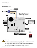
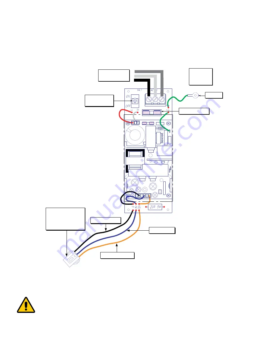
WIRING DIAGRAM: 

AUTO-SWITCH POWER SUPPLY

AC Supply

115 to 220 VAC

DC Power Cable:

Connect to

Annunciator Module

G

N

L

L - Live

N - Neutral

G - Ground

Fuse (1 AMPw)

Ground

Toggle Switch

CAUTION: 

1.  Verify that power has been switched off prior to working on the alarm

2.  Risk of electric shock, disconnect power at the circuit breaker before removing power supply shield

Orange (15 VDC)

Blue (5 VDC)

Ground

Fuse (1 AMPw)

AC Supply

115 to 220 VAC

ON/OFF

Toggle Switch

DC Power Cable:

Connect to the 

female connector 

on the LCD Module

L - Live

N - Neutral

G - Ground

Black (Ground)

Содержание Alert-3 LCD v2.3

Страница 1: ...Operating Maintenance Manual Alert 3 LCD Alarm v2 7 1ST FLOOR ROOM 12 2ND FLOOR ROOM 25 3RD FLOOR ROOM 37 MAINTEN EXT 302 4TH FLOOR ROOM 47 5TH FLOOR ROOM 58 ...

Страница 2: ...x 7 For Local Sensor Only 7 Standing Pressure Test 7 Sensor 7 8 Local 7 Remote 8 Frame Assembly 8 System Power Supply 9 Sensor Module 9 10 Gas Display 9 Local 10 Remote 10 LCD Display Module 10 LCD Display Setup 11 Closing the Frame Assembly 11 Programming Gas Locations 12 15 Clear Erase Programming Gas Location Text 15 Model Numbers 16 Spare Part Numbers 17 18 Sensors 17 DISS Kits 17 Accessories ...

Страница 3: ...ower Supply Appendix C 24 Wiring Diagram LCD Display Board Alarm Buzzer Appendix D 25 Wiring Diagram LCD Display Board Local Sensor Appendix E 26 Wiring Diagram LCD Display Board Remote Sensor Appendix F 27 Wiring Diagram LCD Display Board Master Module Appendix G 28 Technical Specifications Appendix H 29 Wiring ...

Страница 4: ...and surveillance systems The alarm has been designed to provide user flexibility and reliability This manual shall enable the customer to install use and maintain the alarm appropriately There is one MUTE or PUSH TO TEST button located on the front face of the LCD alarm The button has two functions to silence an alarm that has occurred and to view the audible alarm sound level at high and low set ...

Страница 5: ...f the LCD alarm Modules are factory mounted on a hinged frame assembly for ease of installation and maintenance Field programmable push buttons for adjustment of HI and LOW set points LCD Alarm available in 1 to 8 gases SHIPMENT DETAILS When you receive an Alert 3 LCD alarm from Amico Corporation the package will consist of three main sections the Alarm Back Box Sensors and the Frame Assembly THE ...

Страница 6: ...emote Buzzer for applications requiring a remote audible alarm master alarm or a Building Management System SENSOR MODULE The Sensor Module contains the transducer which converts the source of the pressure vacuum into a digital signal that is displayed on the LCD alarm The sensor module shall be housed in an anodized aluminum and nickel plated brass enclosure to act as a barrier against interferen...

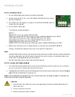
Страница 7: ... Care Facilities or CSA Z7396 1 Medical Gas Pipeline Systems Inspect all joints for leaks and make certain each gas is piped to a correspondingly labeled gas service STEP 4 SENSOR A LOCAL inside the back box i Locate the gas specific sensor module to be installed ii In the back box there are color coded gas labels located under the DISS Demand Check Valves Each label identifies where each sensor m...

Страница 8: ... with frame in a plastic bag This will allow the frame assembly and back box to be fastened securely together NOTE FRAME ASSEMBLY SHOULD BE CLOSED AND FRAME PLATE SHOULD BE ATTACHED RIGHT AFTER THE INSTALLATION WHEN INSTALLATION IS COMPLETED AND ALARM IS READY TO USE PEEL OFF THE LCD SCREEN PROTECTOR P a g e 1 2 3 The sensor module contains a gas specific DISS fitting Push the sensor module hex nu...

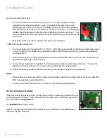
Страница 9: ...s iii Connect the AC power to the terminal blocks as shown in the wiring diagram see Appendix B CAUTION 1 Verify that power has been switched off prior to working on the alarm 2 Risk of electric shock Disconnect power at the circuit breaker before removing power supply shield STEP 7 SENSOR MODULE A GAS DISPLAY on screen location The location of gases displayed on screen is dependant upon which sen...

Страница 10: ...ppendix E ii Connect a 22 gauge stranded shielded and twisted pair cable ONLY up to 1000 ft 304 8 m Knockouts are provided throughout the alarm back box iii Connect the red wire from the cable to the terminal on the display module marked Sensor Connect the black wire to terminal Sensor as shown in the wiring diagram see Appendix E iv Repeat the above procedures with the remaining sensor modules us...

Страница 11: ...ld now be displayed If any errors occur repeat the steps above NOTE Hold the MUTE button for twenty 20 seconds to display current low and high set points and the audible alarm Once the audible alarm stops the LCD Alarm will go back to normal Do not press mute button while on test mode If press it will repeatedly show current set points Press the Setup button B1 in order to make corrections go back...

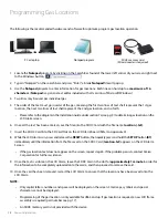
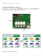
Страница 12: ...x A 8 While the LCD Alarm is on press and release the RESET button then quickly press and hold the SETUP button B1 immediately until the information from the file saved on the SDHC Card location txt appears on the LCD Alarm Screen If the gas location text does not appear on the screen repeat step 6 If the problem persists contact Amico Corporation for further assistance 9 Once the text is visible ...

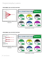
Страница 13: ...LOOR ROOM 58 6TH FLOOR ROOM 65 ENGINEER EXT 225 1ST FLOOR ROOM 12 3RD FLOOR ROOM 37 MAINTEN EXT 302 4TH FLOOR ROOM 47 6TH FLOOR ROOM 65 ENGINEER EXT 225 Notepad File Notepad File Updated Display on LCD Alarm Updated Display on LCD Alarm PROGRAMMING GAS LOCATIONS FOR 6 GAS PROGRAMMING GAS LOCATIONS FOR 4 GASES OUT OF 6 GAS Skip two lines ...

Страница 14: ...OOM 65 1ST FLOOR 2ND FLOOR ROOM 25 4TH FLOOR 5TH FLOOR ROOM 58 6TH FLOOR ROOM 65 ENGINEER EXT 225 Notepad File Notepad File Updated Display on LCD Alarm Updated Display on LCD Alarm PROGRAMMING GAS LOCATIONS TO SKIP LINES PROGRAMMING GAS LOCATIONS TO SKIP LINES Skip one line Skip one line Skip one line Skip two lines ...

Страница 15: ...T Button then quickly press and hold the SETUP Button B1 immediately until the information disappears on the LCD Alarm Screen NOTE A SD Card is not needed for this process 1ST FLOOR ROOM 12 2ND FLOOR ROOM 25 3RD FLOOR ROOM 37 MAINTEN EXT 302 4TH FLOOR ROOM 47 5TH FLOOR ROOM 58 6TH FLOOR ROOM 65 ENGINEER EXT 225 Reset Button Setup Button ...

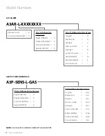
Страница 16: ...emote Local R Conversion Retrofit C The X Defines theType of Gas Oxygen O Medical Air A MedVac V Nitrous Oxide 2 Nitrogen N Carbon Dioxide C WAGD NFPA W AGSS CSA ISO E Instrument Air I GAS Defines theType of Gas Oxygen OXY Medical Air AIR MedVac VAC Nitrous Oxide N2O Nitrogen NIT Carbon Dioxide CO2 WAGD NFPA WAG AGSS CSA ISO AGS Instrument Air IAR The L Defines the Language English NFPA U English ...

Страница 17: ...3P SENS U IAR Sensor Module USA IAR Eng Alert 3 Model Number Description A3 MAN ALM ENG Alert 3 Alarm Manual English A2P POWER V2 Power Supply Module A2P BOXASS 3LCD Alarm Back Box Assembly 3 Station A3P FRMASS E LCD Alert 3 Alarm Frame Assembly LCD English ISO A3P FRMASS U LCD Alert 3 Alarm Frame Assembly LCD US NFPA A2P PIPE Pressure Module Pipe Assembly A3P DEMO CASE Alert 3 Demo Alarm SENSORS ...

Страница 18: ...Frame 5 Station White Colour A3P BOX 7 FILL AL 3 Alarm Box Filler Frame 7 Station White Colour A3P CONKIT GANG 3 For 3 Gang Conv Trim Plate White Colour A3P CONKIT GANG 4 For 4 Gang Conv Trim Plate White Colour A3P CONKIT GANG 5 For 5 Gang Conv Trim Plate White Colour A3P CONKIT GANG 7 For 7 Gang Conv Trim Plate White Colour A2P CON FTUBE AL 2 3 Conv Sensor Flexible Tubing A2P CONKIT CHEAN 1 Conv ...

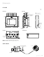
Страница 19: ... Brass 1 25 HEX 1 4 6 NPT 7 50 191 6 375 162 7 3 16 182 2 1 10 53 34 0 81 20 57 Punched hole for electrical power cord or cable 0 75 19 05 2 5 44 45 2 5 63 5 1 75 63 5 1 2 30 48 1 25 4 0 875 22 23 10 7 271 78 0 75 19 05 1 25 4 Bottom View 1 25 31 75 NOTE DISS demand check valves by 1 4 6 NPT supplied with each sensor NOTE LCD Alarm itself is 8 lbs Each sensor is 1 lb Brazing Filler Metal AWS Spec ...

Страница 20: ...ected to the LCD module a Ensure that the DC power plug is firmly in its socket on the LCD alarm b Replace the System Power Supply unit if all the above steps fail to resolve the problem Power light is ON however there is no display on LCD screen Power failure on screen a Remove all transducers and reset power by switching the power supply OFF then ON b Check the DC power voltage If DC power drops...

Страница 21: ...o the LCD alarm by using wiring diagram in Appendix D or Appendix E Requires calibration Re calibrate pressure reading see pg 11 step 9 iv CURRENT OFF SET Defective sensor a Disconnect the sensor and make sure there is no moisture or water It is recommended to check the filter b Replace the sensor module Defective LCD display Replace the LCD alarm Display shows NO SENSORS or MISSING No sensor s ar...

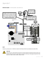
Страница 22: ...m static electricity ensure to discharge body static before installing the Medical Gas Alarm and Sensors 3 Warranty void if push button is broken or if the frame assembly is disassembled Buzzer DC Connector Reset Button Microchip Orange 15 VDC Blue 5 VDC Sensor Terminal LCD Power Mute Button located on reverse side of board Generic Alarm Dry Contact Fault Indicator to Building Management System Ma...

Страница 23: ... Toggle Switch CAUTION 1 Verify that power has been switched off prior to working on the alarm 2 Risk of electric shock disconnect power at the circuit breaker before removing power supply shield Orange 15 VDC Blue 5 VDC Ground Fuse 1 AMPw AC Supply 115 to 220 VAC ON OFF Toggle Switch DC Power Cable Connect to the female connector on the LCD Module L Live N Neutral G Ground Black Ground ...

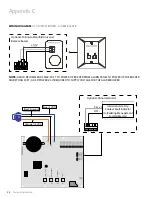
Страница 24: ...d Toggle Switch NOTE NC COM NO 12V GND NO COM NC 12V GND Optional To Amico Manifold Universal Remote Buzzer NO COM NC 12V GND NC COM N NO CO NOTE AMICO RECOMMENDS MAX 50 FT TO POWER UP BUZZER FROM ALARM PANEL TO POWER UP THE BUZZER MORE THAN 50 FT A A3P POWER V4 IS REQUIRED TO SUPPLY VOLTAGE FOR THE ALARM BUZZER Optional Abnormal Alarm Generic Alarm Dry Contact Fault Indicator to Building Manageme...

Страница 25: ...AM Pw Ground Toggle Switch OXYGEN 22 Gauge twisted pair shielded cable 6 8 0 1m 0 2m supplied CAUTION To protect from static electricity ensure to discharge body static before installing the Medical Gas Alarm and sensors NOTE Do not ground the shield drain wire at sensor or inside alarm panel back box Sensor Module Black Red 6 8 0 1m 0 2 m 22 gauge stranded shielded and twisted pair cable supplied...

Страница 26: ...le Switch NOTE For multiple sensors a multi conductor 22 gauge stranded shielded and twisted pair cable ONLY must be used Appendix E Sensor Module 6 8 0 1m 0 2 m 22 gauge stranded shielded twisted pair cable supplied Marrette the sensor cable in a junction box supplied by others to the installation cable supplied by others 22 gauge stranded shielded twisted pair cable ONLY must be used up to a dis...

Страница 27: ...Master module Turn OFF dip switches for any unused points LocationSW 2 S1 S2 CAUTION For Master Alarm source equipment signal wires must be connected to normally closed dry contacts No electrical voltage can be present and contacts must be closed during normal equipment operation When contacts are open an alarm condition will be activated Sensor Module Master Module Source Equipement DISS 22 gauge...

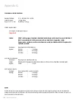
Страница 28: ...onduit Distance Maximum 1000 ft 304 8 m Signal 30 VDC 1 0 Amps 60 VDC 0 3 Amps 125 VAC 0 5 Amps LCD Alarm to Master Distance Maximum 10 000 ft 3 000 m Cable Minimum 22 gauge stranded wire does not have to be shielded twisted pair Signal 5 VDC 5 µA LCD Generic Alarm Output Dry Contacts NC open on Alarm Rating 30 VDC 1 0 Amps 60 VDC 0 3 Amps 125 VAC 0 5 Amps Appendix G NOTE For Master Alarm source e...

Страница 29: ...d be used for connecting sensors or master alarms to source equipment 8 To protect from static electricity ensure to discharge body static before installing the Medical Gas Alarm and Sensors 9 Do not ground the shield drain wire at sensor or inside alarm panel back box 10 Electrical cable should not run below sensors or behind the alarm box to protect from radio frequencies and EMI 2 Low Voltage w...

Страница 30: ......

Страница 31: ......

Страница 32: ...T ALERT3 LCD ALRM 04 27 2022 Amico Corporation 85 Fulton Way Richmond Hill ON L4B 2N4 Canada 600 Prime Place Hauppauge NY 11788 USA Toll Free Tel 1 877 462 6426 Tel 905 764 0800 Fax 905 764 0862 Email info amico com www amico com ...

Отзывы: