P R E S S U R E AND S
E
N
S
O
R
MODULES
2. PRESSURE DISPLAY AND SENSOR MODULES
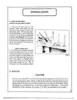
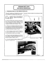
These two modules are installed concurrently. The sensor module contains the transducer which
is connected to the brass quick-disconnect.
SENSOR M O D U L E
NOTE: A L W A Y S HOLD THIS MODULE
BY T H E B R A S S QUICK-DICONNECT
FITTING. (Fig. 4)
(a) Plug the brass male connector protruding
from the top of the sensor module into the
female receptacle in the box in the wall. The
connector should click into place. (Fig. 4)
(b) Remove the display module from its box
and plug the connector atthe end of the tail into
the appropriate connector on the motherboard
just below the sensor module. (Fig. 5)
(c) Flip the display module so that it hangs by
its cable just below the box. The circuit with all
the components should now be visible.
(d) Plug the small cable leading from the end
of the sensor module into terminal J2 on the
pressure display module. (Fig. 4)
(e) The unit has been factory calibrated and
requires no adjustments.
PRESSURE D I S P L AY M O D U L E
F i g .
4
Fig. 5
5

