


NGX Ultra Jukebox
11
22022626 Rev A
Testing the Unit
Initial Set Up
When all of the network connections have been
made, boot up the jukebox. The first time you turn on
the jukebox with a new hard drive, you will see the
Local Music Configuration Screen, which lists the
available local music configurations that can be
installed on the jukebox. You will be prompted to
select one from the list of available configurations.
This selection can be changed at any time by
pressing the SERVICE button on the Computer Core,
and then touching
System Setup
->
Advanced
Administration
->
Local Music Configuration
.
Touch the
View
button to display a dialog box listing
all of the albums in the selected list. Some albums
may appear grayed out; this means that some or all
of the songs in the album are not currently stored on
this jukebox. If a list with grayed albums is installed,
the grayed albums will start being downloaded to the
jukebox within 24 hours (as long as the jukebox is
connected). If the jukebox becomes disconnected,
any songs not yet downloaded will be unavailable to
patrons.
Touch the
Install
button to display a dialog box
prompting you to install the selected list. To install the
selected list, touch the Install button at the bottom of
the dialog box.
Testing the Touchscreen, Bill and Coin
Acceptor(s), and Credit Card Reader
Touchscreen –
Every time a new hard drive is
installed, the touchscreen should be calibrated.
Follow these steps to calibrate.
1. Press the “CALIBRATE” button on the Computer
Core (see
Figure 1-B
) to launch the calibration
program.
2. Close the currency door and make sure it is
locked.
3. Follow the directions on the screen, touching the
center of the targets, and then touching different
areas on the screen. If the cursor follows your
movement, touch
YES
to exit.
Bill/Coin Acceptor(s) and Credit Card Reader –
(NOTE: Credit Card functionality requires a
broadband Internet connection).
1. Press the “SERVICE” button on the Computer
Core to enter Service Mode.
2. Touch the
Diagnostics
button.
3. Touch
Credit Device Tests
.
4. To test the bill acceptor(s), insert a $1, $5, $10,
and $20 bill (into each bill acceptor, if the jukebox
has two) and check the screen to make sure
proper credit is displayed.
5. To test the coin acceptor (if installed), deposit
coins into the coin slot and verify proper credit is
displayed on the screen.
6. To test the credit card reader, swipe a valid credit
card and check that the screen displays the last
four digits of the credit card.
7. When finished, touch the
Back
button to return to
the Main Menu.
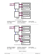
Testing the Network
Enter Service Mode by pressing and releasing the
“SERVICE” button on the Computer Core. To test the
network:
1. Touch the
System Setup
button on screen and
then touch
Advanced Administration
.
2. On the Advanced Administration Screen, touch
Configure Server
. Then touch the
Test
Connection
button. This test confirms the
jukebox can connect to AMI’s server (“Server
Found”), and authenticate a connection with
AMI’s server (“Connected”).
3. If the connection is successful, you will see “
Yes
”
next to “
Server Found
” and “
Connected
”. If the
connection fails, you will see “
No
”. If the
connection fails, check the settings on the
Network Information Screen (
Diagnostics
–>
Network Information
). This screen will allow you
to check the IP Configuration and run LAN and
WAN tests.
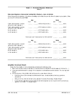
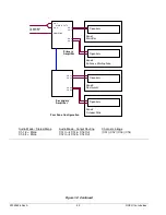
Testing the Audio
NOTE
: For operators pre-testing the jukebox in their
own facility, any features in the application
associated with the network will not work unless the
jukebox is connected to the Internet.
1. If the jukebox is not in Service Mode, press the
“SERVICE” button on the Computer Core to enter
Service Mode.
2. Add one (or more) credits to play a song and test
the audio. Touch
Cash Management
and then
touch
Credit Management
.
3. Touch the box under “Credits” and a pop-up box
will display.
4. Touch
Clear
to remove the “0” from the box.
5. Touch
1
(or more) and then touch
Update
.
6. Touch
Save
on the Credit Management Screen.
7. Touch
Exit Service Mode
.
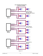
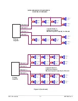
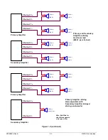
8. After connecting speakers to the jukebox (see
section C), play a local music selection to test the
audio.
Содержание NGX ULTRA
Страница 6: ...22022626 Rev A 4 NGX Ultra Jukebox This page is intentionally left blank ...
Страница 25: ...NGX Ultra Jukebox 23 22022626 Rev A Section D Service Maintenance Recommended Routine Maintenance ...
Страница 28: ...22022626 Rev A 26 NGX Ultra Jukebox This page is intentionally left blank ...
Страница 40: ...22022626 Rev A 38 NGX Ultra Jukebox This page is intentionally left blank ...
Страница 50: ...AMI Entertainment Network LLC 4147 Eastern Avenue SE Grand Rapids Michigan 49508 ...


