


21
a. The source wires (
L1, L2, L3
) are connected with terminals of AC contactor marked
L1, L2, L3
respectively.
b. Terminals
4#
of control button is connected with terminals of AC contactor marked
L1
; wire
3#
is connected with
A1
terminals of control button.
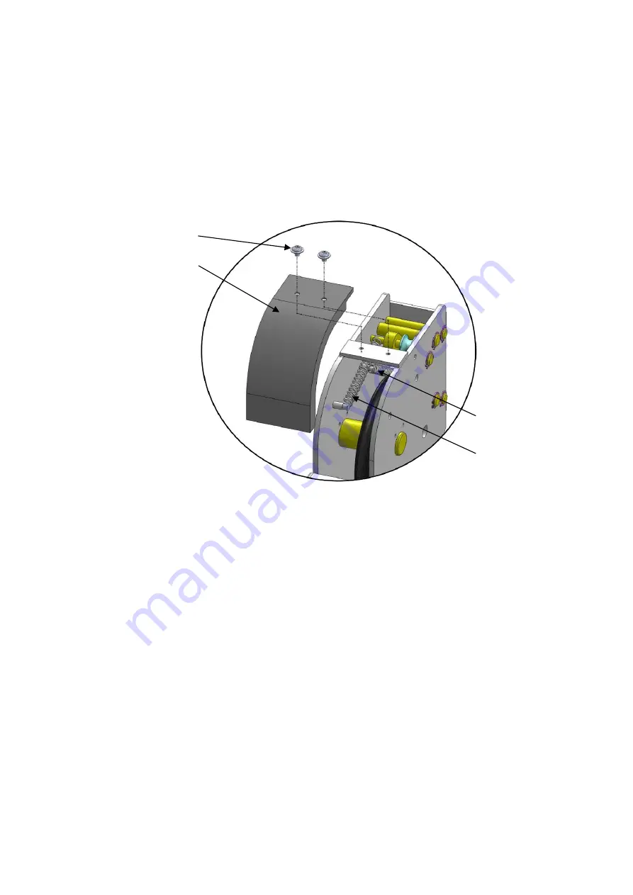
M. Install spring and safety cover of cross beam
(See Fig. 28).
N. Install drive-in ramp, jack tray and plastic oil pans
(See Fig. 29)
.
59
57
58
60
Fig. 28
Содержание 409-HP
Страница 1: ...409 P 409 HP ...
Страница 28: ...26 CROSS BEAM 3 1 201 3 4 7 9 12 13 15 14 11 10 5 6 8 62 2 Fig 37 ...
Страница 29: ...27 CYLINDERS Manual power unit 220V 60Hz Fig 38 Fig 39 ...
Страница 30: ...28 Illustration of hydraulic valve Manual hydraulic power unit 110V 60Hz single phase Fig 41 Fig 43 Fig 40 ...
Страница 40: ...38 AMGO HYDRAULIC CORPORATION Tel 803 505 6410 Fax 803 505 6410 1931 Jo Rogers Blvd Manning South Carolina USA ...
Страница 41: ...39 Manual Part No 72147401 Revision Date 2017 10 ...


