13
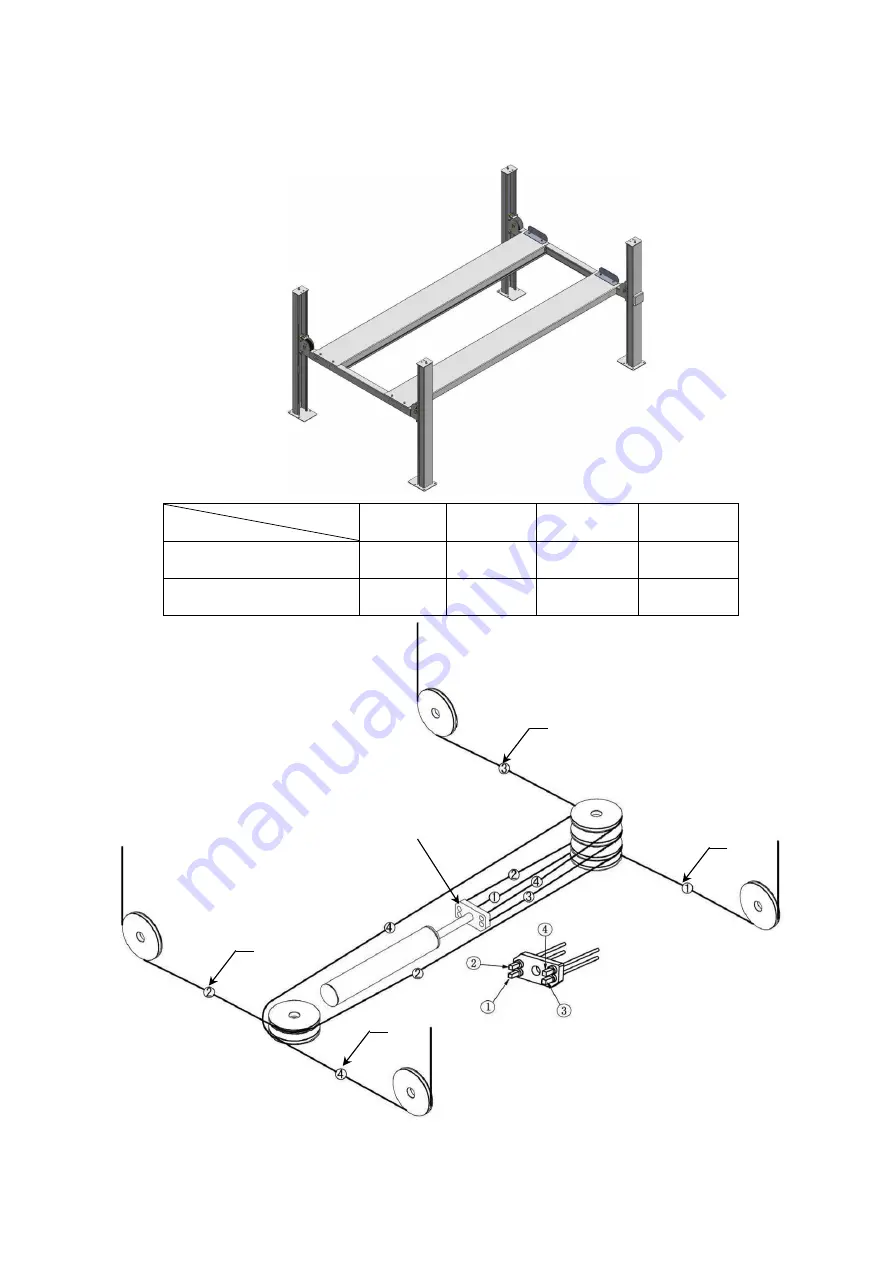
H. Illustration for cable installation
1. Pass through the cables from the platform to the columns according to the number
of the cables
(See Fig. 19)
.
NO.
Cable
①
②
③
④
Length for 409-P
(inc. connecting fitting)
124”
363 1/4
”
187”
301 3/8”
Length for 409-HP
(inc. connecting fitting)
132 3/4”
383 1/4”
194 3/4”
321 1/4”
Cable installation diagram
A
C
B
35
36
37
38
Install the cylinder
connecting plate as shown
and pay attention to the
direction of unfilled corner
on the plate.
D
Fig. 19
A
B
C
D
Содержание 409-HP
Страница 1: ...409 P 409 HP ...
Страница 28: ...26 CROSS BEAM 3 1 201 3 4 7 9 12 13 15 14 11 10 5 6 8 62 2 Fig 37 ...
Страница 29: ...27 CYLINDERS Manual power unit 220V 60Hz Fig 38 Fig 39 ...
Страница 30: ...28 Illustration of hydraulic valve Manual hydraulic power unit 110V 60Hz single phase Fig 41 Fig 43 Fig 40 ...
Страница 40: ...38 AMGO HYDRAULIC CORPORATION Tel 803 505 6410 Fax 803 505 6410 1931 Jo Rogers Blvd Manning South Carolina USA ...
Страница 41: ...39 Manual Part No 72147401 Revision Date 2017 10 ...


