background image

ReFlex Power™ Controller 

ReFlex Power™ 

3-8 

M380056-01 Rev L 

3.3.6


E

NVIRONMENTAL 

C

HARACTERISTICS


O

PERATING 

T

EMPERATURE


Standard: 0 to 50 °C 

Extended Range Option: -10 to 55 °C 

O

PERATING 

A

LTITUDE


Standard: 0 to 6,500 ft  

Extended Range Option: 0 to 15,000 ft 

O

PERATING 

H

UMIDITY


95% non-condensing  

O

PERATING 

S

HOCK


Class 3 MIL-PRF-28800F  

O

PERATING 

V

IBRATION


Class 3 MIL-PRF-28800F  

O

PERATION 

W

ITHOUT 

F

ULLY 

P

OPULATED 

M

AINFRAME


If Mainframe is not fully populated with modules, filler panels must be 
installed in empty slots to maintain proper airflow and structural integrity.  

N

ON

-O

PERATING 

T

EMPERATURE


-40 to 71 °C  

N

ON

-O

PERATING 

A

LTITUDE


0 to 50,000 ft 

N

ON

-O

PERATING 

S

HOCK


Class 3 MIL-PRF-28800F  

N

ON

-O

PERATING 

V

IBRATION


Class 3 MIL-PRF-28800F  

Содержание Elgar ReFlex Power

Страница 1: ...M380056 01 Rev L www programmablepower com ReFlex Power Operation Manual...

Страница 2: ......

Страница 3: ......

Страница 4: ......

Страница 5: ...Notice of Copyright ReFlex Power Operation Manual Cover and Warranty Info 2007 2010 AMETEK Programmable Power Inc All rights reserved Exclusion for Documentation UNLESS SPECIFICALLY AGREED TO IN WRITI...

Страница 6: ...ii This page intentionally left blank...

Страница 7: ...nnel and equipment safety Always ensure that facility AC input power is de energized prior to connecting or disconnecting any cable In normal operation the operator does not have access to hazardous v...

Страница 8: ...iv This page intentionally left blank...

Страница 9: ...tions of AMETEK is opened modified or disassembled in any way without AMETEK s consent or is used in combination with items articles or materials not authorized by AMETEK The Buyer may not assert any...

Страница 10: ...vi This page intentionally left blank...

Страница 11: ...IEW 1 9 1 3 4 INPUTCHARACTERISTICS OVERVIEW 1 9 1 3 5 ENVIRONMENTALCHARACTERISTICS 1 11 1 3 6 REGULATORYCOMPLIANCE 1 12 1 4 MINIMUM REQUIREMENTS 1 12 1 5 REFLEX POWER FIRMWARE COMPATIBILITY 1 13 SECTI...

Страница 12: ...ACTERISTICS 3 6 3 3 2 GENERAL CHARACTERISTICS 3 6 3 3 3 INPUT OUTPUT CONNECTIONS 3 6 3 3 4 COMMAND SETS DRIVERS 3 7 3 3 5 MECHANICAL CHARACTERISTICS 3 7 3 3 6 ENVIRONMENTAL CHARACTERISTICS 3 8 3 3 7 R...

Страница 13: ...CONNECTION CONFIGURATIONS 4 31 4 5 4 DEFAULT OPERATIONAL CONDITIONS 4 38 4 5 5 INITIAL FUNCTIONAL TESTS 4 39 4 6 CALIBRATION 4 44 4 6 1 SCOPE 4 44 4 6 2 RECOMMENDED CALIBRATION EQUIPMENT 4 44 4 6 3 CA...

Страница 14: ...5 3 4 GENERAL CHARACTERISTICS 5 7 5 3 5 INPUT OUTPUT CONNECTIONS 5 7 5 3 6 COMMAND SETS DRIVERS 5 8 5 3 7 MECHANICAL CHARACTERISTICS 5 8 5 3 8 ENVIRONMENTAL CHARACTERISTICS 5 9 5 3 9 REGULATORY AGENC...

Страница 15: ...ISTICS 6 10 6 3 5 GENERAL CHARACTERISTICS 6 11 6 3 6 INPUT OUTPUT CONNECTIONS 6 12 6 3 7 COMMAND SETS DRIVERS 6 14 6 3 8 MECHANICAL CHARACTERISTICS 6 14 6 3 9 ENVIRONMENTAL CHARACTERISTICS 6 15 6 3 10...

Страница 16: ...ETS DRIVERS 7 11 7 3 6 MECHANICAL CHARACTERISTICS 7 11 7 3 7 ENVIRONMENTAL CHARACTERISTICS 7 12 7 4 INSTALLATION 7 13 7 4 1 INITIAL INSPECTION 7 13 7 4 2 LOCATION CONSIDERATIONS 7 13 7 4 3 INSTALLATIO...

Страница 17: ...ISTANCE CALIBRATION PART VOF V 7 51 7 6 18 HPALIAIBOARD CALIBRATION 7 53 7 6 19 LPALCALPOT CALIBRATION 7 55 7 6 20 CURRENT CALIBRATION FOR LPAL 7 57 7 6 21 LPALLOW RANGE CURRENT CALIBRATION 7 60 7 6 2...

Страница 18: ...FPDC Interface Connector Pinout 5 18 Table 5 3 FPDC DC Output Connector Pinout 5 20 Table 5 4 Wire Data 5 22 Table 5 5 Calibration Power Connector 5 29 Table 5 6 Load Resistors 5 33 Table 5 7 Output...

Страница 19: ...Slot Numbering Assignments Empty Mainframe Front View 4 18 Figure 4 6 ACPS Output Connector Front Panel View and Wiring Diagram 4 22 Figure 4 7 Interface Connector Front Panel View and Wiring Diagram...

Страница 20: ...dalone Output Configuration 6 45 Figure 6 16 Parallel Output Configuration 6 46 Figure 6 17 Series Output Configuration 6 48 Figure 6 18 Series Parallel Output Configuration 6 50 Figure 6 19 Calibrati...

Страница 21: ...M380056 01 Rev L xvii This page intentionally left blank...

Страница 22: ......

Страница 23: ...les all controlled through one Controller module This programmable system utilizes digital control loops patent pending that allow tailoring of performance to match application requirements and mainta...

Страница 24: ...power processing stages to minimize size weight and maximize power density Their performance has also been optimized in areas of accuracy output slew rates and ripple noise Power factor correction PFC...

Страница 25: ...ries or parallels in a series operation LXI conformant IVI drivers Web server 16 bit programming and measurement Power Factor Corrected PFC Universal inputs AC 50 60 Hz 400 Hz DC single phase three ph...

Страница 26: ...of the Mainframe with its interface connectors The Mainframe chassis provides twelve slots for interface with the backplane modules slide on integral guides and are secured with front panel captive th...

Страница 27: ...eference Guide P N M380056 04 OPTIONAL ACCESSORIES Mainframe Interconnect cable assembly 36 5380054 01 Interconnect cable assembly 97 5380054 02 Interconnect cable assembly 135 5380054 03 Input power...

Страница 28: ...he system 1 3 1 PRODUCT MATRIX OVERVIEW Table 1 1 Module Complement Model Type Voltage Rating Current Rating Power Rating Module Width RFP D1016 021 xxxx Low power DC module 0 16 V 0 20 6 A 330 W Sing...

Страница 29: ...ny empty slot and there are no restrictions to the placement order of the modules except for parallel and multiphase groups Within each Mainframe the backplane also distributes the AC DC input power t...

Страница 30: ...CTIONS Series Parallel groups are also allowed The requirements for configuring the group are a combination of those for the dedicated series and parallel groups presented above the parallel modules m...

Страница 31: ...x 15 D 4 5 lb RFP D2033 030 xxxx High power DC module 2 8 H x 6 75 H x 15 D 9 0 lb RFP D2050 020 xxxx High power DC module 2 8 H x 6 75 H x 15 D 9 0 lb RFP D2050 025 xxxx High power DC module 2 8 H x...

Страница 32: ...tral only DC Input 270VDC nominal 210 300VDC Current Sum of individual module input currents Apparent Input Power Sum of individual module input power Frequency 47 63Hz 380 420Hz and DC Power Factor P...

Страница 33: ...conditions of temperature altitude shock vibration and input power OPERATING ENVIRONMENTAL CONDITIONS Temperature Standard 0 to 50 C Extended Range Option 10 to 55 C Altitude Standard 0 to 6 500 feet...

Страница 34: ...1 3 6 REGULATORY COMPLIANCE EMC compliance is per EN 61326 1997 and safety compliance is per IEC 61010 1 satisfies MIL PRF 28800F Test Environment CISPR 16 1 Conducted Susceptibility IEC 1000 4 6 Con...

Страница 35: ...0 and revision 3 000 000 assets When powering up a system with mixed revision assets installed the red Fault LED will blink on a version 3 controller if a version 2 module is detected If a version 3 M...

Страница 36: ...nclosure Multiple Mainframes could be combined into an extended system all controlled by a single Controller module and using common communications and software programming The system is compatible wi...

Страница 37: ...by the requirement to allow the dissipation of high power in a small package from supplies as well as active loads Each module has integral fans optimized for the amount of heat that must be eliminate...

Страница 38: ...onnect Cable Assembly 135 P N 5380054 03 Input Power Cable Assembly P N 5380317 01 AC Input Mating Connector P N 5380318 01 Filler Panel single width P N 5380059 01 2 3 SPECIFICATIONS The ReFlex Power...

Страница 39: ...4 2 RFP L3500 750 xxxx 500VDC 30A 750W Triple 4 2 RFP L3500 375 xxxx 500VDC 15A 375W Triple 4 2 RFP F1000 001 xxxx 5V 5VDC 15 15VDC 10 5A 3 3A 165W Single 1 4 RFP C1LAN 000 xxxx Single 1 4 2 3 2 INPUT...

Страница 40: ...ccepts single width double width and triple width modules 1kW maximum output power per slot BACKPLANE CONNECTORS Circuit Board mounted connectors with integral guide pins CONNECTOR ACCESSIBILITY AC DC...

Страница 41: ...tandard 0 to 6 500 ft Extended Range Option 0 to 15 000 ft OPERATING HUMIDITY 95 non condensing OPERATING SHOCK Class 3 MIL PRF 28800F OPERATING VIBRATION Class 3 MIL PRF 28800F OPERATION WITHOUT FULL...

Страница 42: ...tallation Category II Pollution Degree 2 Class II Equipment for Indoor Use Only EMC COMPLIANCE EMC Directive EN 61326 1998 ELECTROSTATIC DISCHARGE IEC 61000 4 2 RADIATED RF IMMUNITY IEC 61000 4 3 FAST...

Страница 43: ...e Department where an associate will provide instructions for repair or replacement of the unit 2 4 2 LOCATION CONSIDERATIONS The ReFlex Power Mainframe is designed for rack mounting using slides or r...

Страница 44: ...MAINFRAME INSTALLATION DRAWINGS Refer to Figure 2 1 for profile and Figure 2 2 for top view outline drawings showing dimensional information for the Mainframe Figure 2 1 Mainframe Profile with Dimensi...

Страница 45: ...to Figure 2 3 for the orientation of a module and Mainframe during installation 1 Ensure that the AC DC input power is disconnected before installing or removing any module s 2 Insert the module into...

Страница 46: ...owed frequency range is 50 60 400Hz The DC input is based on a nominal 270VDC with an operating range from 210VDC to 300VDC CAUTION Connecting to a wye source at 230 400VAC must be from line to neutra...

Страница 47: ...the backplane connectors of a set of four slots is connected in parallel and is supplied by one pair of the AC DC input lines In a double width and triple width module the module connector is located...

Страница 48: ...input line the module will draw power Balancing of phase currents can be achieved only if the power modules are installed into the Mainframe so that there is an equal distribution of current between t...

Страница 49: ...208VAC 3 Delta L1 F Phase A Slot 1 4 L1 RTN E Phase B L2 A Phase B Slot 5 8 L2 RTN G Phase C L3 B Phase C Slot 9 12 L3 RTN C Phase A GND D Ground Slot 1 12 Safety GND Chassis GND Ground Chassis 200 2...

Страница 50: ...draw For example a Mainframe with six HPDC modules each 2U wide would have modules plugged into the following locations slot 2 slot 4 slot 6 slot 8 slot 10 and slot 12 see Figure 2 5 The slots would b...

Страница 51: ...t most 12A RFP A30XK 875 xxxx triple 3 right most 12A RFP L3500 750 xxxx RFP L3500 375 xxxx triple 3 right most 1 1A The maximum output power per single group of four slots is produced when two HPDC 1...

Страница 52: ...not have any means to disconnect it from the AC DC input service The front panel POWER switch of the Controller module in the Mainframe does not disconnect the AC DC input line from the modules or Mai...

Страница 53: ...separate dedicated safety ground wire must be connected to the Mainframe rear panel safety ground stud Operating the ReFlex Power system with the safety ground wire disconnected could result in a sho...

Страница 54: ...nout and functions of the connector are presented in Table 2 4 The associated maximum wire gauge for connector terminations and recommended maximum wire lengths are presented in Table 2 10 Table 2 5 p...

Страница 55: ...perating the ReFlex Power system with the safety ground wire disconnected could result in a shock hazard Figure 2 7 J5 AC DC Input Connector Mainframe Rear Panel View Table 2 4 J5 AC DC Input Connecto...

Страница 56: ...ingle ReFlex Power Controller module in an extended system These connectors are dedicated to interconnecting Mainframes and do not contain any signals that are intended for external user interface The...

Страница 57: ...485 logic levels referenced to BGND 12 DIG1_I O_H_OUT Input Output digital I O differential signal RS 485 logic levels referenced to BGND 13 DIG1_I O_L_OUT Input Output digital I O differential signa...

Страница 58: ...the DIGITAL CTRL IN J2 connector The pinout and functions of the connector are presented in Table 2 7 The associated maximum wire gauge for connector terminations and recommended maximum wire lengths...

Страница 59: ...vels referenced to BGND 12 DIG1_I O_H_IN Input Output digital I O differential signal RS 485 logic levels referenced to BGND 13 DIG1_I O_L_IN Input Output digital I O differential signal RS 485 logic...

Страница 60: ...YNCL OUT Input output SYNC bus differential signal with SYNC H RS 485 logic levels referenced to module AGND U CURRH OUT Input output CURR bus differential signal with CURR L 10V analog signal referen...

Страница 61: ...SYNCL IN Input output SYNC bus differential signal with SYNC H RS 485 logic levels referenced to module AGND U CURRH IN Input output CURR bus differential signal with CURR L 10V analog signal referenc...

Страница 62: ...4 10 WIRE SELECTION Input output wiring must have a current carrying capacity compatible with the current rating of the ReFlex Power system The maximum current rating of a wire is dependent on the mat...

Страница 63: ...ble total voltage drop for the load wiring under the maximum peak current The resistance of the load wiring must be determined for the sum total length of the output lead and the return lead The total...

Страница 64: ...error and fault messages Indicate interface communication link activity The module operates as part of a remotely controlled system It utilizes the ReFlex Power Mainframe backplane for input power dis...

Страница 65: ...Mbps supported The command interface for the RFPC can be direct via Standard Commands for Programmable Instrumentation SCPI that conforms to the IEEE 488 2 specification Alternatively a set of up to t...

Страница 66: ...ogramming manual P N M380056 03 to be used in conjunction with this manual Quick Reference Guide P N M380056 04 3 2 4 CONTROLS AND INDICATORS The RFPC module operates within the ReFlex Power system an...

Страница 67: ...the switch will turn off the output power for all AC DC modules and input power for load modules open the isolation relays if present and disable internal logic power However the power switch does no...

Страница 68: ...ller M380056 01 Rev L 3 5 Figure 3 2 ReFlex Power Controller Rear CAUTION Do not hot swap permanent damage may occur if any ReFlex Power module is installed or removed when the AC power is on See Sect...

Страница 69: ...operating temperature and will turn off all the modules The maximum internal temperature is typically 85 C 3 3 2 GENERAL CHARACTERISTICS INPUT VOLTAGE RANGE 103 5 253VAC with AC input 270VDC nominal...

Страница 70: ...d 1999 command language MODULE RESPONSE DESCRIPTION SCPI Standard 1997 command language COMMAND EXECUTION TIME Command execution time is a function of the module type and grouping See specific module...

Страница 71: ...DITY 95 non condensing OPERATING SHOCK Class 3 MIL PRF 28800F OPERATING VIBRATION Class 3 MIL PRF 28800F OPERATION WITHOUT FULLY POPULATED MAINFRAME If Mainframe is not fully populated with modules fi...

Страница 72: ...IES Installation Category II Pollution Degree 2 Class II Equipment for Indoor Use Only EMC COMPLIANCE EMC Directive EN 61326 1998 ELECTROSTATIC DISCHARGE IEC 61000 4 2 RADIATED RF IMMUNITY IEC 61000 4...

Страница 73: ...it is removed from the shipping container Check for shipping damage such as dents scratches or distortion of the enclosure If external damage is evident there may be internal damage as well Immediatel...

Страница 74: ...nframe from the front of the chassis Refer to Figure 3 3 for the orientation of a module and Mainframe during installation 1 Ensure that the AC DC input power is disconnected before installing or remo...

Страница 75: ...al or line to line depending on the available source voltage The power source voltage must be within the range of 103 5 253VAC at 47 63Hz and 400Hz The input voltage ranges are continuous and do not r...

Страница 76: ...switch or circuit breaker must be located close to the ReFlex Power system within reach of the operator and clearly labeled as the disconnection device In multi Mainframe systems each Mainframe has an...

Страница 77: ...includes the following Bill of Material Item AMETEK Part No Description Qty Manufacturer Part No Manufacturer Suggested Source s 1 856 993 07 Plug RJ45 Turn 26482 NI 1 RJF6MN Amphenol Socapex PEI Gen...

Страница 78: ...twisted shielded cables Figure 3 4 Interface Connector Front Panel View and Interface Connector Wiring Diagram Table 3 1 Control Connector Pinout Pin Type Signal Function Signal Level 1 A RI Remote I...

Страница 79: ...TYPES A Bi Directional Digital I O Signals internally pulled up to 5V DC Externally to be pulled low 0 5 VDC relative to the designated signal return signal type C B Internal relay contact that is con...

Страница 80: ...data negative twisted differential pair with TX IEEE 802 3 3 RX Receive data positive twisted differential pair with RX IEEE 802 3 4 NA N A 5 NA N A 6 RX Receive data negative twisted differential pa...

Страница 81: ...t Red LED indicates either the Controller or any power module has detected a high level system fault 3 Bus Green LED indicates Controller internal communication is in process 4 Interface connector pro...

Страница 82: ...rameters are set to default values RFPC LAN Parameters are at either Factory Default DHCP enabled Auto IP enabled or User Default settings All Modules are in initial power up default state relays if p...

Страница 83: ...s will sequentially cause the following to occur The RFPC and all power modules installed will turn on their Power indicators green indicating their internal power supplies are on The RFPC and all pow...

Страница 84: ...itializing before continuing 4 Verify communications with the RFPC by issuing the SCPI command IDN The RFPC should respond with its identification string 5 Verify that all of the modules have complete...

Страница 85: ...ReFlex Power Controller ReFlex Power 3 22 M380056 01 Rev L This page intentionally left blank...

Страница 86: ...d control communications interface Through the ReFlex Power Controller module communications with the user host controller is established for programming read back and configuration control All connec...

Страница 87: ...s without compromising performance or the controls feature set The mechanical design is ruggedized for harsh environments including mobile applications as well as general purpose industrial and labora...

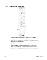
Страница 88: ...al P N M380056 03 Quick Reference Guide P N M380056 04 4 2 3 CONTROLS AND INDICATORS The AC power supply module operates within the ReFlex Power system as part of an automated test system so there are...

Страница 89: ...AC Power Supplies ReFlex Power 4 4 M380056 01 Rev L Figure 4 1 ACPS Module Front Panel 875VA...

Страница 90: ...reduced accuracy immediately following power on All accuracy specifications are plus minus variations around the nominal parameter values unless otherwise noted Unless otherwise specified requirements...

Страница 91: ...Power 4 6 M380056 01 Rev L 4 3 1 PRODUCT MATRIX Model Voltage Full Scale Rating Current Full Scale Rating Power Rating Module Width ACPS 0 140V 0 280V 7 0A 3 5 A 875 VA Triple 4 2 Figure 4 3 Power Li...

Страница 92: ...urs at constant line load and temperature Voltage Load Regulation RMS load regulation is 0 1 of full scale for 100 resistive load change Voltage Line Regulation RMS line regulation is 0 1 of full scal...

Страница 93: ...he load module will continue to maintain output but with reduced programming accuracy to 5 Misconnection of the sense leads shall not result in an output voltage in excess of the over voltage protecti...

Страница 94: ...phase would be B phase and C phase counterclockwise phaser rotation is assumed therefore the phase angle offset is leading the master reference Programming Accuracy 1 degree 1 degree kHz for balanced...

Страница 95: ...Watt Apparent Power Range version 3 0 and up only 0 to 1000 VA Apparent Power Accuracy 1 0 5 kHz Apparent Power Resolution 0 1 VA Reactive Power Range version 3 0 and up only 0 to 1000 VAR Reactive P...

Страница 96: ...rammable from 0 4 to 106 of full scale output current Accuracy 3 of full scale Resolution 0 027 of full scale Over Temperature Over temperature protection is implemented with hardware monitors that se...

Страница 97: ...connected in parallel any module could be a master adjacent modules to the right when viewed from the front of the unit of the master would be slaves paralleling could be extended between mainframes c...

Страница 98: ...imensions 4 2 inch wide 6 75 inch high and 15 inch deep Weight 11 4 pound maximum Cooling Provisions Operation at maximum limits of output power ambient temperature and altitude requires adequate airf...

Страница 99: ...y 95 non condensing Operating Shock Class 3 MIL PRF 28800F Operating Vibration Class 3 MIL PRF 28800F Operation Without Fully Populated Mainframe If Mainframe is not fully populated with modules fille...

Страница 100: ...s Installation Category II Pollution Degree 2 Class II Equipment for Indoor Use Only EMC Compliance EMC Directive EN 61326 1998 Electrostatic Discharge IEC 61000 4 2 Radiated RF Immunity IEC 61000 4 3...

Страница 101: ...ing container and filler material should be saved for inspection Forward a report of the damage to the Customer Care Department where an associate will provide instructions for repair or replacement o...

Страница 102: ...ntation of a module and Mainframe during installation 1 Ensure that the AC DC input power is disconnected before installing or removing any module s 2 Insert the module into the mainframe rear panel f...

Страница 103: ...le source voltage The power source voltage must be within the range of 85 264VAC at 47 63Hz and 400Hz or 210 300VDC The input voltage ranges are continuous and do not require any manual setup The modu...

Страница 104: ...d if the same load is applied to the set of modules in each group The load applied to a particular AC DC input line is dependent on the location of the modules in the Mainframe slots The slots are gro...

Страница 105: ...hassis 200 208VAC 220 230 240VAC 3 Wye L1 F Phase A Slot 1 4 L1 RTN E Neutral L2 A Phase B Slot 5 8 L2 RTN G Neutral L3 B Phase C Slot 9 12 L3 RTN C Neutral GND D Ground Slot 1 12 Safety GND Chassis G...

Страница 106: ...ual for recommendations 4 4 6 AC DC INPUT DISCONNECT DEVICE The ReFlex Power system does not have any means to disconnect it from the AC DC input service The front panel POWER switch of the Controller...

Страница 107: ...c Ind http www connectpositronic com default cfm 4 856 214 09 Conn 9P DSUB 20 24AWG Crimp Male 1 SD9M1000Z Positronic Industries Positronic Ind http www connectpositronic com default cfm 5 856 247 10...

Страница 108: ...re 4 6 ACPS Output Connector Front Panel View and Wiring Diagram Table 4 2 AC Output Connector Pinout Pin Name Function Signal Level A1 OUT Output module source connected to A3 280VAC 440Vpk maximum t...

Страница 109: ...r to the section Noise and Impedance Effects The sense leads should be a twisted pair of at least AWG 22 wire and may require shielding in high noise environments Connect the shield to the shield grou...

Страница 110: ...856 247 10 Wire size Maximum gauge 20 AWG recommended Length maximum 10 meters can be extended subject to the environment cable type and interface circuits Figure 4 7 Interface Connector Front Panel...

Страница 111: ...e that exceeds the rating of the wire WIRE CURRENT CAPACITY Table 4 4 shows maximum current ratings based on a cable of three conductors that will produce an approximate 30 C temperature rise above am...

Страница 112: ...rature T R20 C resistance m at 20 C T temperature of wire C The voltage drop per output or return lead could be calculated using the following equation V I x L x R20 C x 1 0 004 x T 20 C where V total...

Страница 113: ...variations in the load itself 4 5 OPERATION The AC power supply module function within the ReFlex Power system under remote control through a host controller The ReFlex Power Controller module serves...

Страница 114: ...ER LED green input AC DC power applied to module FAULT LED red internal abnormal operating condition detected output disabled and isolation relay opened BUS LED green Internal bus communication establ...

Страница 115: ...h the backplane between the modules as well as the digital control communications to implement a master slave control interface The routing of signals in this interface requires that parallel modules...

Страница 116: ...of the load If the load resistance is greater than the voltage setting divided by the current setting the output voltage would be regulated in voltage mode If the load resistance is less than the volt...

Страница 117: ...ing divided by the current setting If the load resistance increases to where the load voltage attempts to exceed the voltage setting the output voltage is then regulated to the programmed voltage sett...

Страница 118: ...les can be connected in parallel The paralleled supplies operate in a master slave configuration where the master controls the output voltage and total current and provides control signals through the...

Страница 119: ...re the output current equally Fault shutdown is coordinated across all modules a fault within any module of the group will result in shutdown of all modules CAUTION The outputs of paralleled modules m...

Страница 120: ...ReFlex Power AC Power Supplies M380056 01 Rev L 4 35 Figure 4 11 Parallel Output Configuration...

Страница 121: ...The outputs of the modules must be hardwired externally while all internal control signal connections are configured automatically when the multi phase group is set up through software In order not t...

Страница 122: ...ReFlex Power AC Power Supplies M380056 01 Rev L 4 37 Figure 4 12 Multiphase Output Configuration with Wye Load Connection...

Страница 123: ...AC Power Supplies ReFlex Power 4 38 M380056 01 Rev L Figure 4 13 Multi phase Output Configuration with Delta Load Connection...

Страница 124: ...rogrammable mode Output state off Output isolation and remote sense relays open Frequency set to 60 Hz RESET CONDITIONS If a module is reset with the SCPI command RST n where n is the module address t...

Страница 125: ...d then back to slow speed In the following paragraphs commands include a channel number n The channel number corresponds to the slot of the ReFlex Power Mainframe where the module is located counting...

Страница 126: ...Connect appropriate instrumentation for measuring the output voltage and current as well as a load Perform the power on verification test per the section Power On Check Turn on the isolation and remo...

Страница 127: ...of the group Although the example is for two modules it could be extended to a greater number by listing additional parameter slot numbers n SYST GRO DEF PAR n1 n2 5 Verify that the parallel group has...

Страница 128: ...andalone Configuration 2 Connect the outputs for multi phase operation per the section Parallel Configuration Ensure that the outputs and remote sense are appropriately hardwired prior to issuing any...

Страница 129: ...ure that the actual values of the output parameters are within specifications of the programmed values The default frequency is 60 Hz 9 Query the values of the output parameters with the following com...

Страница 130: ...ld compromise the validity of the calibration Instrument Requirements Recommended Model AC Voltmeter Resolution 6 1 2 digits Agilent 34401A Current Shunt RFP A301K 875 XXXX and RFP A305K 875 XXXX 50m...

Страница 131: ...tes cal pot for the voltage range low This calibration is done with the AC current meter connected to the output lead of the AC power supply 1 Connect the AC current meter to the output lead of the po...

Страница 132: ...CAL n CALPOTS GAIN CURR value 6 Finish the gain pot calibration CAL n CALPOTS GAIN CALC 7 Send the system error query command to make sure calibration was successful SYST ERR 8 If there is no error re...

Страница 133: ...alibration of the offset pot CAL n CALPOTS OFFSET CALC 5 Start the calibration of the gain pot CAL n CALPOTS GAIN START 6 Set the load box to approximately 3 25 Amps Wait for the current to stabilize...

Страница 134: ...ReFlex Power AC Power Supplies M380056 01 Rev L 4 49 To query the gain pot set value CAL n CALPOTS GAIN 11 Reset the unit RST n...

Страница 135: ...to maximum limit CAL n OUTP CURR PROT COUNTS 4000 7 Set the voltage to zero CAL n OUTP VOLT COUNTS 0 8 Set the current to maximum limit CAL n OUTP CURR COUNTS 4000 9 DAC range is from 0 to 65535 Ther...

Страница 136: ...then using the value returned a Hex number as a starting point walk the DC voltage toward 0 0 volts by increasing the value if the DC value is negative and decreasing the value if it is positive One c...

Страница 137: ...range of the power supply to high SOUR n VOLT RANGE 1 6 Set the OVP supervisory to limit 12000 CAL n OUTP VOLT PROT COUNTS 12000 7 Set the OCP supervisory to maximum limit CAL n OUTP CURR PROT COUNTS...

Страница 138: ...sure the DC output voltage if the voltage is not 0 0 10mVolts read the DAC offset value with CAL n OUTP DAC OFFSET and then using the value returned a Hex number as a starting point walk the DC voltag...

Страница 139: ...ear and reset commands CLS RST n 3 Perform the voltage ADC offset calibration CAL n MEAS VADC OFFSET CALC 4 Send the system error query command to make sure calibration was successful SYST ERR 5 If th...

Страница 140: ...Set the voltage range of the power supply to high SOUR n VOLT RANGE 1 4 Perform the voltage ADC offset calibration CAL n MEAS VADC OFFSET CALC 5 Send the system error query command to make sure calibr...

Страница 141: ...Set the voltage range of the power supply to low SOUR n VOLT RANGE 0 4 Perform the voltage ADC offset calibration CAL n MEAS IADC OFFSET CALC 5 Send the system error query command to make sure calibra...

Страница 142: ...Set the voltage range of the power supply to high SOUR n VOLT RANGE 1 4 Perform the voltage ADC offset calibration CAL n MEAS IADC OFFSET CALC 5 Send the system error query command to make sure calib...

Страница 143: ...4 Perform the voltage ADC offset calibration CAL n MEAS OFFSET CALC 5 Send the system error query command to make sure calibration was successful SYST ERR 6 If there is no error returned at the syste...

Страница 144: ...1 4 Perform the voltage ADC offset calibration CAL n MEAS OFFSET CALC 5 Send the system error query command to make sure calibration was successful SYST ERR 6 If there is no error returned at the syst...

Страница 145: ...power supply to low SOUR n VOLT RANGE 0 6 Set the current to maximum limit CAL n OUTP CURR COUNTS 4000 7 Turn the unit on OUTP n STATE 1 8 Set the OVP supervisory to limit 20261 CAL n OUTP VOLT PROT C...

Страница 146: ...e output voltage using the AC voltmeter Enter the measured voltage using following command CAL n OUTP VOLT FIVEPOINT4 value 4 18 Program the output voltage to 95 of the full scale voltage CAL n OUTP V...

Страница 147: ...AC Power Supplies ReFlex Power 4 62 M380056 01 Rev L RST n...

Страница 148: ...imum limit CAL n OUTP CURR COUNTS 4000 5 Turn the unit on OUTP n STATE 1 6 Set the OVP supervisory to limit 20261 CAL n OUTP VOLT PROT COUNTS 20261 7 Set the OCP supervisory to maximum limit CAL n OUT...

Страница 149: ...following command CAL n OUTP VOLT FIVEPOINT4 value 4 16 Program the output voltage to 95 of the full scale voltage CAL n OUTP VOLT COUNTS 18332 17 Wait for AC voltage to stabilize Measure the output...

Страница 150: ...TATE 1 5 Program the output voltage to count 17000 CAL n OUTP VOLT COUNTS 17000 6 Send the calibration command to start the internal calibration CAL n OUTP LDF CALC 7 Turn the unit off OUTP n STATE 0...

Страница 151: ...TATE 1 5 Program the output voltage to count 17000 CAL n OUTP VOLT COUNTS 17000 6 Send the calibration command to start the internal calibration CAL n OUTP LDF CALC 7 Turn the unit off OUTP n STATE 0...

Страница 152: ...125Volt AC 5 Issue clear and reset commands CLS RST n 6 Set the voltage range of the power supply to low SOUR n VOLT RANGE 0 7 Set the OVP supervisory to limit 20261 CAL n OUTP VOLT PROT COUNTS 20261...

Страница 153: ...18 Wait for AC current to stabilize Measure the output current using the AC meter Enter the measured current CAL n OUTP CURR FIVEPOINT4 value 4 19 Program the output current to 95 of the full scale c...

Страница 154: ...ReFlex Power AC Power Supplies M380056 01 Rev L 4 69 Query the current calibration points CAL n OUTP CURR FIVEPOINT 26 Reset the unit RST n...

Страница 155: ...0Volts AC 5 Issue clear and reset commands CLS RST n 6 Set the voltage range of the power supply to high SOUR n VOLT RANGE 1 7 Set the OVP supervisory to limit 20261 CAL n OUTP VOLT PROT COUNTS 20261...

Страница 156: ...lize Measure the output current using the AC meter Enter the measured current CAL n OUTP CURR FIVEPOINT4 value 4 19 Program the output current to 95 of the full scale current CAL n OUTP CURR COUNTS 44...

Страница 157: ...AC Power Supplies ReFlex Power 4 72 M380056 01 Rev L 26 Reset the unit RST n...

Страница 158: ...et commands CLS RST n 6 Set the voltage range of the power supply to low SOUR n VOLT RANGE 0 7 Turn the unit on OUTP n STATE 1 8 Set the hall calibration data to the default value CAL n OUTP FREQ CURR...

Страница 159: ...n OUTP FREQ CURR4 value 4 20 Set the output frequency to 3000Hz SOUR n FREQ 3000 21 Wait for AC current to stabilize Measure the output current using the AC meter Enter the measured current CAL n OUT...

Страница 160: ...ower AC Power Supplies M380056 01 Rev L 4 75 28 If there is no error returned at the system error query command then save the calibration data CAL n UNLOCK 6867 CAL n STORE CAL n LOCK 29 Reset the uni...

Страница 161: ...reset commands CLS RST n 6 Set the voltage range of the power supply to high SOUR n VOLT RANGE 1 7 Turn the unit on OUTP n STATE 1 8 Set the hall calibration data to the default value CAL n OUTP FREQ...

Страница 162: ...easure the output current using the AC meter Enter the measured current using following command CAL n OUTP FREQ CURR4 value 4 20 Set the output frequency to 3000Hz SOUR n FREQ 3000 21 Wait for AC curr...

Страница 163: ...mand CAL n OUTP FREQ CALC 27 Send the system error query command to make sure calibration was successful SYST ERR 28 If there is no error returned at the system error query command then save the calib...

Страница 164: ...reset commands CLS RST n 6 Set the voltage range of the power supply to low SOUR n VOLT RANGE 0 7 Turn the unit on OUTP n STATE 1 8 Set the hall calibration data to the default value CAL n OUTP FREQ C...

Страница 165: ...current meter Enter the measured current using following command CAL n OUTP FREQ CURR4 value 4 20 Set the output frequency to 820Hz SOUR n FREQ 820 21 Wait for AC current to stabilize Measure the outp...

Страница 166: ...Send the system error query command to make sure calibration was successful SYST ERR 28 If there is no error returned at the system error query command then save the calibration result with the follow...

Страница 167: ...put 5 Issue clear and reset commands CLS RST n 6 Set the voltage range of the power supply to high SOUR n VOLT RANGE 1 7 Turn the unit on OUTP n STATE 1 8 Set the hall calibration data to the default...

Страница 168: ...he output current using the AC current meter Enter the measured current CAL n OUTP FREQ CURR4 value 4 20 Set the output frequency to 820Hz SOUR n FREQ 820 21 Wait for AC current to stabilize Measure t...

Страница 169: ...he voltage calibration CAL n OUTP FREQ CALC 27 Send the system error query command to make sure calibration was successful SYST ERR 28 If there is no error returned at the system error query command t...

Страница 170: ...crete control signal interface are available on the module front panels The module utilizes high frequency power conversion for high efficiency to maximize power density and realize light weight and s...

Страница 171: ...Low ripple noise Constant voltage regulation Power Factor Correction PFC Universal inputs AC 50 60 Hz 400 Hz DC single phase three phase Opto isolated remote turn on and shutdown of outputs Integral o...

Страница 172: ...e and Controller module for data communications and power input All output load connections and discrete control interface to the user application are accessible on the front panel of the module Also...

Страница 173: ...Fixed Power DC Power Supply ReFlex Power 5 4 M380056 01 Rev L Figure 5 2 Rear View of Typical DC Supply Module...

Страница 174: ...ations are valid following calibration at 25 C 5 C 5 3 1 PRODUCT MATRIX Model Output Current Rating Power Rating FPDC 5V DC 10 A 50W 5V DC 5 A 25W 15V DC 3 A 45W 15V DC 3 A 45W 5 3 2 OUTPUT CHARACTERI...

Страница 175: ...5VDC and 15VDC have reached at least 50 of their nominal output level POWER OFF SEQUENCE The module when commanded to turn off shall sequence the 4 output voltage outputs such that the 5VDC turns off...

Страница 176: ...75 A maximum POWER FACTOR 0 95 at full output load 0 75 at 20 output load decreasing to 0 3 at no load EFFICIENCY 60 minimum FRONT PANEL INDICATORS OUTPUT LED green output enabled and isolation relay...

Страница 177: ...ide 6 75 inch high and 15 inch deep WEIGHT 4 7 pound maximum COOLING PROVISIONS Operation at maximum limits of output power ambient temperature and altitude requires adequate airflow of 15 CFM through...

Страница 178: ...MIDITY 95 non condensing OPERATING SHOCK Class 3 MIL PRF 28800F OPERATING VIBRATION Class 3 MIL PRF 28800F OPERATION WITHOUT FULLY POPULATED MAINFRAME If Mainframe is not fully populated with modules...

Страница 179: ...TEGORIES Installation Category II Pollution C 2 Class II Equipment for Indoor Use Only EMC COMPLIANCE EMC Directive EN 61326 1998 ELECTROSTATIC DISCHARGE IEC 61000 4 2 RADIATED RF IMMUNITY IEC 61000 4...

Страница 180: ...e If external damage is evident there may be internal damage as well Immediately contact the carrier and file a claim for concealed damage In addition the shipping container and filler material should...

Страница 181: ...for the orientation of a module and Mainframe during installation 1 Ensure that the AC DC input power is disconnected before installing or removing any module s 2 Insert the module into the mainframe...

Страница 182: ...300VDC The input voltage ranges are continuous and do not require any manual setup CAUTION Exceeding the maximum rated AC DC input voltage could result in damage to the module The module can produce f...

Страница 183: ...the modules in the Mainframe slots The slots are grouped in sets of four Slot 1 4 Slot 5 8 and Slot 9 12 Slot 1 is the left most slot as viewed from the front Figure 5 4 Each of the four slots is sup...

Страница 184: ...Chassis GND Ground Chassis 200 208VAC 220 230 240VAC 3 Wye L1 F Phase A Slot 1 4 L1 RTN E Neutral L2 A Phase B Slot 5 8 L2 RTN G Neutral L3 B Phase C Slot 9 12 L3 RTN C Neutral GND D Ground Slot 1 12...

Страница 185: ...The front panel POWER switch of the Controller module in the Mainframe does not disconnect the AC DC input line from the modules or Mainframe Ensure that a suitable disconnecting device is incorporate...

Страница 186: ...9M1000Z Positronic Industries Positronic Ind http www connectpositronic com default cfm 5 856 247 10 Conn Backshell 9P DSUB 2 PC 1 D9000Z00 Positronic Industries Positronic Ind http www connectpositro...

Страница 187: ...RVED 8 RESERVED 9 RESERVED 1 Enable signal is internally pulled up to 5V with a 10 K resistor To enable the module the signal is pulled low 0 5V with respect to the ENAB RTN signal this may also be ac...

Страница 188: ...Maximum 10 meters Pins A1 A4 Positronic Industries P N MC4012D AMETEK P N 856 745 52 Wire size Maximum gauge 12 AWG recommended Length Maximum 10 meters Backshell Positronic Industries P N D37000Z00...

Страница 189: ...Positive Output derived after disconnect relay A4 5V RTN 5V Return DC Output Connector Accessories AMETEK P N 5380449 01 FPDC Module 9ft Unterminated DC Output Cable Assembly AMETEK P N 5380449 03 FPD...

Страница 190: ...of the ReFlex Power system The maximum current rating of a wire is dependent on the materials used in its construction and is primarily limited by the insulation The current must be limited so that t...

Страница 191: ...ring to voltage drop from the output terminals of the FPDC module to the load must be considered The wire gauge must be selected to maintain an acceptable total voltage drop for the load wiring under...

Страница 192: ...in reducing the parasitic inductance of the cable This improves the dynamic response characteristics at the load by maintaining a low source impedance at high frequencies Also with long load wires the...

Страница 193: ...voltages are enabled or isolation relays are closed 2 Power Indicator Green LED lights when AC DC input power is applied to the module 3 Fault Indicator Red LED lights when an abnormal internal operat...

Страница 194: ...o the load are made at the front panel output connector terminals Ensure that a wire gauge is utilized that can carry the programmed current without overheating REMOTE SENSING Remote sensing of the ou...

Страница 195: ...5 8 Each Output Voltage Configuration 5 5 4 DEFAULT OPERATIONAL CONDITIONS POWER ON CONDITIONS When the FPDC power supply module is first powered on the following parameters are set to factory defaul...

Страница 196: ...r module should respond with its identification string 9 Verify communications with the ReFlex Power FPDC power supply module by issuing an SCPI IDN n where n is a channel number that corresponds to t...

Страница 197: ...eriod Calibration Power Connector Mating connector 21 pin D_SUB special Positronic Subminiature D CBC Series CBC21WA4M1000Z crimp signal contacts Four male contacts high current male contact ratings M...

Страница 198: ...5 V 5 DMM Stub A2 5 V RTN 14 DMM Stub A3 5 V 6 DMM Stub A4 5 V RTN 15 DMM Stub Either enable the FPDC module if there is an available means or create another special connector to insert in the contro...

Страница 199: ...ount of nn from the X value returned in Step 2 will change the output by 30 mV 4 Repeat Step 3 until the measured voltage is within the range from 14 970 to 15 030 volts 5 CALIBRATION 1 Connect the DM...

Страница 200: ...output voltage is within the range from 14 970 to 15 030 volts SAVING CALIBRATION If none of the supplies required adjustment during the calibration procedures the Calibration Procedure is complete I...

Страница 201: ...nd use the retaining screws to secure both 8 The FPDC module is ready for operation Turning on the RFPC power switch controls power 5 7 PERFORMANCE VERIFICATION 5 7 1 INTRODUCTION Performance verifica...

Страница 202: ...es and verify the no load output voltage is within specification Add the load resistors to measure the load regulation Connect the DSO across the leads to verify the ripple and noise specifications Th...

Страница 203: ...uding the probes ground will cause erroneous measurements Table 5 9 Ripple and Noise Output Ripple and Noise peak peak 5VDC 150 mV 5VDC 80 mV 15VDC 150 mV 15VDC 150 mV 5 7 7 VOLTAGE ON OFF SEQUENCING...

Страница 204: ...the user load and discrete control signal interface are available on the module front panels The modules utilize high frequency power conversion for high efficiency to maximize power density and real...

Страница 205: ...ns as well as general purpose industrial and laboratory rack mount ATE 6 2 1 GENERAL FEATURES High power density Small size light weight Up to twelve modules per Mainframe Digital control loops 16 bit...

Страница 206: ...uick Reference Guide P N M380056 04 6 2 3 CONTROLS AND INDICATORS The DC power supply modules operate within the ReFlex Power system as part of an automated test system so there are no user manual con...

Страница 207: ...DC Power Supplies ReFlex Power 6 4 M380056 01 Rev L Figure 6 1 ReFlex Power DC Front Panel 16 20 single width model shown...

Страница 208: ...ReFlex Power DC Power Supplies M380056 01 Rev L 6 5 Figure 6 2 ReFlex Power DC Front Panel 450 2 double width model shown...

Страница 209: ...at reduced accuracy immediately following power on All accuracy specifications are plus minus variations around the nominal parameter values unless otherwise noted Unless otherwise specified requireme...

Страница 210: ...ED WITH 20HZ TO 20MHZ BANDWIDTH RFP D1016 021 XXXX 5mV RMS 25mV Pk Pk RFP D1065 5A1 XXXX 6mV RMS 18mV Pk Pk RFP D2033 030 XXXX 15mV RMS 60mV Pk Pk RFP D2050 020 XXXX 20mV RMS 75mV Pk Pk RFP D2050 025...

Страница 211: ...NSIENT Less than 5 of full scale excursion returning to the steady state value within 0 5 of full scale in 2 ms maximum and within DC regulation limits after 10 ms for 10 50 and 90 load step above and...

Страница 212: ...full scale the programmed voltage step change must be correspondingly reduced CURRENT PROGRAMMING RANGE 0 to 102 of full scale CURRENT DIGITAL PROGRAMMING ACCURACY RFP D1016 021 XXXX RFP D1065 5A1 XX...

Страница 213: ...2050 020 XXXX 3mV RFP D2050 025 XXXX 3mV RFP D2120 8A3 XXXX 7mV RFP D2450 2A3 XXXX 28mV CURRENT ACCURACY 0 1 of full scale plus 0 2 of set point at 25 C 5 C CURRENT RESOLUTION RFP D1016 021 XXXX 1 28m...

Страница 214: ...user selectable to be programmable or tracking The default mode of operation is programmable OCP Programmable operation The OCP threshold is programmable from 5 to 120 of full scale output current Tr...

Страница 215: ...ngle phase AC input sinusoidal AC current unipolar DC input continuous DC current RFP D1016 021 XXXX RFP D1065 5A1 XXXX 4A at 103 5VAC 1 5A at 270VDC RFP D2033 030 XXXX RFP D2050 020 XXXX RFP D2120 8A...

Страница 216: ...NEL INDICATORS OUTPUT LED green output enabled and isolation relay closed POWER LED green input AC DC power applied to module FAULT LED red internal abnormal operating condition detected output disabl...

Страница 217: ...connected in series RFP D2033 030 XXXX RFP D2050 020 XXXX RFP D2050 025 XXXX three modules could be connected in series SERIES PERFORMANCE DEGRADATION Conforms to specifications of individual modules...

Страница 218: ...6 75 inch high and 15 inch deep WEIGHT RFP D1016 021 XXXX RFP D1065 5A1 XXXX 4 5 pound maximum RFP D2033 030 XXXX RFP D2050 020 XXXX RFP D2050 025 XXXX RFP D2120 8A3 XXXX RFP D2450 2A3 XXXX 9 0 pound...

Страница 219: ...tended Range Option 0 to 15 000 ft OPERATING HUMIDITY 95 non condensing OPERATING SHOCK Class 3 MIL PRF 28800F OPERATING VIBRATION Class 3 MIL PRF 28800F OPERATION WITHOUT FULLY POPULATED MAINFRAME If...

Страница 220: ...S Installation Category II Pollution Degree 2 Class II Equipment for Indoor Use Only EMC COMPLIANCE EMC Directive EN 61326 1998 ELECTROSTATIC DISCHARGE IEC 61000 4 2 RADIATED RF IMMUNITY IEC 61000 4 3...

Страница 221: ...aled damage In addition the shipping container and filler material should be saved for inspection Forward a report of the damage to the Customer Care Department where an associate will provide instruc...

Страница 222: ...ation 1 Ensure that the AC DC input power is disconnected before installing or removing any module s 2 Insert the module into the Mainframe aligning the guide rails at the rear of the module with the...

Страница 223: ...e input voltage ranges are continuous and do not require any manual setup CAUTION Exceeding the maximum rated AC DC input voltage could result in damage to the module The modules could produce full ra...

Страница 224: ...pplied to a particular AC DC input line is dependent on the location of the modules in the Mainframe slots The slots are grouped in sets of four Slot 1 4 Slot 5 8 and Slot 9 12 Slot 1 is the left most...

Страница 225: ...ND Ground Chassis 200 208VAC 220 230 240VAC 3 Wye L1 F Phase A Slot 1 4 L1 RTN E Neutral L2 A Phase B Slot 5 8 L2 RTN G Neutral L3 B Phase C Slot 9 12 L3 RTN C Neutral GND D Ground Slot 1 12 Safety GN...

Страница 226: ...rame manual for recommendations 6 4 7 AC DC INPUT DISCONNECT DEVICE The ReFlex Power system does not have any means to disconnect it from the AC DC input service The front panel POWER switch of the Co...

Страница 227: ...t No 5380270 01 mates with RFP D1016 021 XXXX and includes the following for both Interface and DC Output connectors Bill of Material Item AMETEK Part No Description Qty Manufacturer Part No Manufactu...

Страница 228: ...P D1016 021 XXXX Interface Connector Pinout PIN NAME FUNCTION SIGNAL LEVEL 1 ENA1 Input module output enable TTL logic level 6 ENA RTN1 Input return for ENA signal connected to Pin 7 8 Signal common 2...

Страница 229: ...ckshell 37P Strt 2 PC 1 D37000Z00 Positronic Industries Positronic Ind http www connectpositronic com default cfm 4 856 214 09 Conn 9P DSUB 20 24AWG Crimp Male 1 SD9M1000Z Positronic Industries Positr...

Страница 230: ...gic level 20 8 TRIG IN RTN Input return for TRIG IN connected to Pin 6 7 Signal common 20 4 RESERVED 9 RESERVED 5 CHAS GND Shield ground Chassis ground 20 1 Enable signal is internally pulled up to 5...

Страница 231: ...ronic Industries Positronic Ind http www connectpositronic com default cfm 3 856 247 39 Conn Backshell 37P Strt 2 PC 1 D37000Z00 Positronic Industries Positronic Ind http www connectpositronic com def...

Страница 232: ...ector Front Panel View and Wiring Diagram Table 6 4 RFP D2033 030 XXXX Interface Connector Pinout PIN NAME FUNCTION SIGNAL LEVEL 1 ENA1 Input module output enable TTL logic level 6 ENA RTN1 Input retu...

Страница 233: ...No Manufacturer Suggested Source s 1 856 214 04 Conn 21P DSUB 8 20AWG Male 1 CBC21WA4M1000Z Positronic Industries Positronic Ind http www connectpositronic com default cfm 2 856 745 51 Contact 10AWG 3...

Страница 234: ...erface circuits RFP D2050 025 XXXX RFP D2050 020 XXXX INTERFACE PINOUT Figure 6 8 RFP D2050 025 XXXX Interface Connector Front Panel View and Wiring Diagram Table 6 5 RFP D2050 025 XXXX RFP D2050 020...

Страница 235: ...anufacturer Part No Manufacturer Suggested Source s 1 856 214 04 Conn 21P DSUB 8 20AWG Male 1 CBC21WA4M1000Z Positronic Industries Positronic Ind http www connectpositronic com default cfm 2 856 745 5...

Страница 236: ...pe and interface circuits RFP D2120 8A3 XXXX INTERFACE PINOUT Figure 6 9 RFP D2120 8A3 XXXX Interface Connector Front Panel View and Wiring Diagram Table 6 6 RFP D2120 8A3 XXXX Interface Connector Pin...

Страница 237: ...t connectors Bill of Material Item AMETEK Part No Description Qty Manufacturer Part No Manufacturer Suggested Source s 1 856 214 04 Conn 21P DSUB 8 20AWG Male 1 CBC21WA4M1000Z Positronic Industries Po...

Страница 238: ...nnector Front Panel View and Wiring Diagram Table 6 7 RFP D2450 2A3 XXXX Interface Connector Pinout PIN NAME FUNCTION SIGNAL LEVEL 1 ENA1 Input module output enable TTL logic level 6 ENA RTN1 Input re...

Страница 239: ...OUTPUT CONNECTOR The DC OUTPUT connector provides terminations for the output and remote sense connections to the load RFP D1016 021 XXXX DC Output Connector Connector Positronic Industries P N CBD13W...

Страница 240: ...10 3A 1 SNS Input remote sense connection for OUT 16V 200V maximum to chassis 20 100 5 SNS RTN Input remote sense connection for OUT RTN 16V 200V maximum to chassis 20 100 4 CHAS GND Shield ground Ch...

Страница 241: ...source connected to A1 65V 300V maximum to chassis 20 40 for 1 5V line drop at 2 55A A4 OUT RTN Output return for output source OUT connected to A2 65V 300V maximum to chassis 20 40 for 1 5V line dro...

Страница 242: ...GAUGE AWG MAXIMUM WIRE LENGTH FT A1 OUT Output module output source connected to A3 33V 200V maximum to chassis 10 75 for 1 5V line drop at 15A A2 OUT RTN Output return for output source OUT connecte...

Страница 243: ...GNAL LEVEL WIRE GAUGE AWG MAXIMUM WIRE LENGTH FT A1 OUT Output module output source connected to A3 50V 200V maximum to chassis 10 90 for 1 5V line drop at 12 5A A2 OUT RTN Output return for output so...

Страница 244: ...6 12 RFP D2120 8A3 XXXX DC Output Connector Pinout PIN NAME FUNCTION SIGNAL LEVEL WIRE GAUGE AWG MAXIMUM WIRE LENGTH FT A1 OUT Output module output source 120V 200V maximum to chassis 10 135 for 1 5V...

Страница 245: ...2A3 XXXX DC Output Connector Pinout PIN NAME FUNCTION SIGNAL LEVEL WIRE GAUGE AWG MAXIMUM WIRE LENGTH FT A1 OUT Output module output source 450V 450V maximum to chassis 20 44 for 1 5V line drop at 2...

Страница 246: ...e module that connects the output terminals to the remote sense terminals This network provides the measurement of the output voltage when the remote sense leads are not connected However since the vo...

Страница 247: ...ased on a cable of three conductors that will produce an approximate 30 C temperature rise above ambient When wiring must operate in areas with an elevated ambient temperature or bundled with other wi...

Страница 248: ...mperature T R20 C resistance m at 20 C T temperature of wire C The voltage drop per output or return lead could be calculated using the following equation V I x L x R20 C x 1 0 004 x T 20 C where V to...

Страница 249: ...e contribution to the ripple noise by the load current Additional filtering with bypass capacitors at the load terminals may be required to bypass the high frequency load currents 6 5 OPERATION The Re...

Страница 250: ...t voltages are enabled or isolation relays are closed 2 POWER Indicator Green LED lights when AC DC input power is applied to the module 3 FAULT Indicator Red LED lights when an abnormal internal oper...

Страница 251: ...trol signals through the backplane between the modules as well as the digital control communications to implement a master slave control interface The routing of signals in this interface requires tha...

Страница 252: ...ings of the series parallel group of modules Only modules of the same model number could be series parallel connected OUTPUT VOLTAGE CURRENT REGULATION The DC power supply module is capable of operati...

Страница 253: ...ent setting the output current is then regulated at the programmed current setting and the output voltage decreases until that condition is satisfied This is the automatic crossover point to constant...

Страница 254: ...egulation is acceptable for all of the loads In general the point of sensing is selected to minimize interaction of the various loads through line drops caused by their load currents CAUTION Operating...

Страница 255: ...ed to be located within the parallel group Individual modules of the group can be separated by empty slots and the group can be extended between two Mainframes The outputs of the modules must be hardw...

Страница 256: ...re connected together The supplies are interconnected with the negative terminal of one supply being connected to the positive terminal of other The output voltage is derived from the positive and neg...

Страница 257: ...ules connected in series The modules will share the output voltage equally The output current is the same for each module Fault shutdown is coordinated across all modules a fault within any module of...

Страница 258: ...put Output Sense Sense Sense Input Load Power Supply2 Power Supply3 Power Supply1 Twisted Pair Cable all senseleadsections shieldedif noisepresent Twisted Pair Cable all power leadsections Single poin...

Страница 259: ...hat single point connections are maintained for the series connected sense leads Figure 6 22 shows the series parallel connection of six units with remote sensing The series paralleled modules are pro...

Страница 260: ...ReFlex Power DC Power Supplies M380056 01 Rev L 6 57 Figure 6 22 Series Parallel Output Configuration...

Страница 261: ...is reset with the SCPI command RST n where n is the module address the following default conditions are set Output configuration unchanged Output voltage 0V Output current 0A Overvoltage protection OV...

Страница 262: ...supply modules the values are as follows Full Scale Voltage RFP D1016 021 XXXX 16 RFP D1065 5A1 XXXX 65 RFP D2033 030 XXXX 33 RFP D2450 2A3 XXXXA3 450 Full Scale Current RFP D1016 021 XXXX 20 6 RFP D...

Страница 263: ...S 1 OUTP n STAT 1 SOUR n VOLT fval SOUR n CURR fval 5 Measure the output voltage and current with the external instruments 6 Ensure that the actual values of the output parameters are within specifica...

Страница 264: ...he slot number of the master module the master module is the left most module of the parallel group SYST GRO CAT PAR 6 Turn on the isolation and remote sense relays turn on the output converters and p...

Страница 265: ...ter slot numbers n SYST GRO DEF SER n1 n2 5 Verify that the series group has been properly set up with the following command The response to the query is a listing of the series group the master modul...

Страница 266: ...I commands 3 Connect appropriate instrumentation for measuring the output voltage and current as well as a load 4 Configure the first set of modules into a parallel group with the following command wh...

Страница 267: ...he parameter 2003 The parameter 2000 n is the sum of 2000 and the slot number of the master module of the series group which also serves as the master of its parallel group SYST GRO CAT SER 9 Turn on...

Страница 268: ...FP D2050 020 XXXX RFP D2050 025 XXXX RFP D2120 8A3 XXXX and RFP D2450 2A3 XXXX Calibration is easily performed through the Controller module interface with SCPI commands requiring only a voltmeter and...

Страница 269: ...MENTS RECOMMENDED MODEL DC Voltmeter Resolution 6 1 2 digits Agilent 34401A Current Shunt RFP D1016 021 XXXX RFP D2033 030 XXXX RFP D2050 020 XXXX and RFP D2050 025 XXXX 10m 0 04 100A RFP D1065 5A1 XX...

Страница 270: ...at the same points where the sense leads are connected 1 Connect a voltmeter across the output terminals Ensure that no load is connected to the output 2 Issue clear and reset commands CLS n RST n 3...

Страница 271: ...he fourth value near 72 5 of full scale count 48852 0 725 768 36185 CAL n OUTP VOLT COUNTS 36185 13 Measure the output voltage with the external voltmeter Enter this as value 4 with the following comm...

Страница 272: ...onnect the external voltmeter to measure the burden voltage of the shunt 2 Issue clear and reset commands CLS n RST n 3 Set the OVP supervisory to non tracking and at maximum range CAL n OUTP VOLT PRO...

Страница 273: ...m the output current to the fourth value near 72 5 of full scale count 32768 0 67258 22039 CAL n OUTP CURR COUNTS 22039 14 Measure the output current with the external shunt Enter this as value 4 with...

Страница 274: ...ReFlex Power DC Power Supplies M380056 01 Rev L 6 71 18 Turn off the output RST n...

Страница 275: ...DC Power Supplies ReFlex Power 6 72 M380056 01 Rev L This page intentionally left blank...

Страница 276: ...d back and configuration control All connections to the user load and analog control signal interface are available on the module front panels The modules utilize FET active current sinks in modular f...

Страница 277: ...daptability through a Mainframe based architecture It extends the modular configuration to high power Active Load assets without compromising performance or the controls feature set The mechanical des...

Страница 278: ...TORS The Active Load modules operate within the ReFlex Power system as part of an automated test system so there are no user manual controls They rely on the Mainframe and Controller module for contro...

Страница 279: ...Active Loads ReFlex Power 7 4 M380056 01 Rev L Figure 7 1 LPAL 375W Front Panel...

Страница 280: ...ReFlex Power Active Loads M380056 01 Rev L 7 5 Figure 7 2 HPAL 750W Front Panel...

Страница 281: ...Active Loads ReFlex Power 7 6 M380056 01 Rev L Figure 7 3 Typical Active Load Rear Panel...

Страница 282: ...d after a 30 minute warm up Modules could be used at reduced accuracy immediately following power on All accuracy specifications are plus minus variations around the nominal parameter values unless ot...

Страница 283: ...y 0 3 of full scale at 25 C 5 C CURRENT MODE Programming Range 375W 0 045 15ADC 750W 0 090 30ADC Digital Programming Resolution 375W model 1 0mA 750W model 2 0mA Digital Programming Accuracy 0 3 of fu...

Страница 284: ...525VDC REDUNDANT OVERVOLTAGE THRESHOLD ACCURACY 3 at 25 C 5 C REDUNDANT OVERCURRENT THRESHOLD Fixed 20A for 375W 40A for 750W REDUNDANT OVERCURRENT THRESHOLD ACCURACY 3 at 25 C 5 C OVERPOWER THRESHOL...

Страница 285: ...HARMONIC Nonlinear AC input current from rectifier capacitor filter CURRENT INRUSH Inrush current protection at power on with AC and DC input 5APK at 115VAC 10A PK at 230VAC 8 5APK at 270VDC FREQUENCY...

Страница 286: ...traction provisions such as levers are provided modules are extracted using front panel mounted handles COOLING PROVISIONS Operation at maximum limits of output power ambient temperature and altitude...

Страница 287: ...t 15 000 feet or with linear power derating from 750W at 6 500 feet to 600W at 15 000 feet OPERATING HUMIDITY 95 non condensing OPERATING SHOCK Class 3 MIL PRF 28800F OPERATING VIBRATION Class 3 MIL P...

Страница 288: ...mage is evident there may be internal damage as well Immediately contact the carrier and file a claim for concealed damage In addition the shipping container and filler material should be saved for in...

Страница 289: ...ly slide the module completely into the Mainframe until the guide pins of the module rear connector engage the mating backplane connector 4 Fully seat the module until the front panel inner surface is...

Страница 290: ...f the Mainframe Refer to the Mainframe manual for recommendations 7 4 6 AC DC INPUT DISCONNECT DEVICE The ReFlex Power system does not have any means to disconnect it from the AC DC input service The...

Страница 291: ...s connected in parallel The groups are connected to separate pair of pins in the Mainframe rear panel AC DC input connector one line and return per connection the connector has six power pins plus gro...

Страница 292: ...ReFlex Power Active Loads M380056 01 Rev L 7 17 Figure 7 5 Slot Numbering Assignment Empty Mainframe Front View...

Страница 293: ...GND Chassis GND Ground Chassis 200 208VAC 220 230 240VAC 3 Wye L1 F Phase A Slot 1 4 L1 RTN E Neutral L2 A Phase B Slot 5 8 L2 RTN G Neutral L3 B Phase C Slot 9 12 L3 RTN C Neutral GND D Ground Slot...

Страница 294: ...enesis http www pei genesis com Arrow Electronics http www arrownac com 2 856 214 09 Conn 9P DSUB 20 24AWG Crimp Male 1 SD9M1000Z Positronic Industries Positronic Ind http www connectpositronic com de...

Страница 295: ...K resistor To enable the module the signal is pulled low 0 5 V with respect to the ENA RTN signal this may also be accomplished by shorting Pin 1 to Pin 6 OPTIONAL INTERFACE CONNECTOR ACCESSORIES AME...

Страница 296: ...necting the source to the input of the Active Load modules A separate pair of wires is routed to measure the voltage at the source terminals where precise measurement of the output voltage is desired...

Страница 297: ...for the Interface connector pinout and wire information 7 4 8 WIRE SELECTION Input output wiring must have a current carrying capacity compatible with the current rating of the ReFlex Power system Th...

Страница 298: ...age drop from the input terminals of the Active Load modules to the Source must be considered The wire gauge must be selected to maintain an acceptable total voltage drop for the load wiring under the...

Страница 299: ...locations and minimize the physical loop area of the untwisted portions Twisting the load wires provides an additional benefit in reducing the parasitic inductance of the cable This improves the dyna...

Страница 300: ...s applied to the module 3 Fault Red LED indicates abnormal internal operating or a protection supervisory active condition output is disabled and the isolation relay is opened 4 Bus Green LED indicate...

Страница 301: ...nt in the source circuit where the voltage is to be precisely measured If a distribution bus is utilized the point of voltage sensing is important to ensure that the voltage measurement is acceptable...

Страница 302: ...urrent protection OCP 120 of full scale current programmable mode Input state off Input isolation and remote sense relays open RESET CONDITIONS If a module is reset with the SCPI command RST n where n...

Страница 303: ...ber corresponds to the slot of the ReFlex Power Mainframe where the module is located counting left to right 1 through 12 For example SOUR n CURR 5 will be SOUR4 CURR 5 for slot 1 SOUR7 CURR 5 for slo...

Страница 304: ...figuration 2 Connect appropriate instrumentation for measuring the input voltage and current as well as a load 3 Perform the power on verification test per the section Power On Check 4 Turn on the iso...

Страница 305: ...that their accuracy is at least four times better than the accuracy of the parameter specification that is begin calibrated If less accurate equipment is utilized measurement uncertainty may be introd...

Страница 306: ...ibration must be performed under controlled environmental conditions Ambient temperature must be within 25 C 5 C Humidity must be less than 80 Allow the unit to warm up for 30 minutes at no load prior...

Страница 307: ...7 6 4 CALPOT CALIBRATION FOR HIGH POWER ACTIVE LOAD HPAL The HPAL calpot calibration is done with the DC current meter connected between the DC power supply and the Active Load This procedure requires...

Страница 308: ...4 Amps Use the Current Shunt and Voltmeter to adjust and measure the current When the current reading is stable enter the current using following command CAL n CALPOTS GAIN CURR value 1 7 This will us...

Страница 309: ...following command CAL n INP CURR FIVEPOINT1 value 1 5 Set the DAC count to 27 5 of its full range CAL n INP CURR COUNTS 16000 6 Wait for the DC current to stabilize After the current reading is stabi...

Страница 310: ...ero CAL12 INP CURR COUNTS 0 14 Send calibration command to make sure that all the DAC counts and current values are valid CAL n INP CURR CALC 15 Send the system error query command to make sure calibr...

Страница 311: ...tabilize After the current reading is stabilized enter the current using following command CAL n INP CURR1 value 1 5 Set the DAC count to 80 of its full range CAL n INP CURR COUNTS 53000 6 Wait for th...

Страница 312: ...ent to stabilize After the current reading is stabilized enter the current using following command CAL n INP CURR1 value 1 5 Set the DAC count to 80 of its full range CAL n INP CURR COUNTS 53000 6 Wai...

Страница 313: ...1 2 Set the conductance count to 0x33333 CAL n INP COND COUNTS 0x33333 3 Set the input DC voltage to 13 Volts After the input DC voltage stabilizes enter the first exact voltage CAL n INP VOLT 1 value...

Страница 314: ...E 1 2 Set the conductance count to 0xCCCC CAL n INP COND COUNTS 0xCCCC 3 Set the input DC voltage to 27 Volts After the input DC voltage stabilizes enter the first exact voltage CAL n INP VOLT 1 value...

Страница 315: ...conductance count to 0x3333 CAL n INP COND COUNTS 0x3333 3 Set the input DC voltage to 54 Volts After the input DC voltage stabilizes enter the first exact voltage using following command CAL n INP VO...

Страница 316: ...E 1 2 Set the conductance count to 0x831 CAL n INP COND COUNTS 0x831 3 Set the input DC voltage to 10 Volts After the input DC voltage stabilizes enter the first exact voltage CAL n INP VOLT 1 value 1...

Страница 317: ...ductance count to 0x15D CAL n INP COND COUNTS 0x15D 3 Set the input DC voltage to 10 Volts After the input DC voltage stabilizes enter the first exact voltage using following command CAL n INP VOLT 1...

Страница 318: ...ive lead Also connect the shunt and the DC current meter between the active load and DC power supply This procedure requires maximum voltage 20 0V and maximum current 17 0 Amps 1 Set the DC input volt...

Страница 319: ...commands CAL n INP CURR 2 value 2 9 Send the calibration command to calculate the gain and offset CAL n INP COND CALC 10 Send the system error query command to make sure calibration was successful SY...

Страница 320: ...ead Also connect the shunt and the DC current meter between the active load and DC power supply This procedure requires maximum voltage 20 0 V and maximum current 3 0Amps 1 Set the DC input voltage to...

Страница 321: ...commands CAL n INP CURR 2 value 2 9 Send the calibration command to calculate the gain and offset CAL n INP COND CALC 10 Send the system error query command to make sure calibration was successful SY...

Страница 322: ...e lead Also connect the shunt and the DC current meter between the active load and DC power supply This procedure requires maximum voltage 50 0 V and maximum current 2 0 Amps 1 Set the DC input voltag...

Страница 323: ...Send the calibration command to calculate the gain and offset CAL n INP COND CALC 10 Send the system error query command to make sure calibration was successful SYST ERR 11 If there is no error retur...

Страница 324: ...negative to negative lead Also connect the shunt and the DC current meter between the active load and DC power supply This procedure requires maximum voltage 50 0V and maximum current 0 5 Amps 1 Set...

Страница 325: ...L n INP CURR 2 value 2 9 Send the calibration command to calculate the gain and offset CAL n INP COND CALC 10 Send the system error query command to make sure calibration was successful SYST ERR 11 If...

Страница 326: ...e to negative lead Also connect the shunt and the DC current meter between the active load and DC power supply This procedure requires maximum voltage 500 0V and maximum current 0 5 Amps 1 Set the DC...

Страница 327: ...AL n INP CURR 2 value 2 9 Send the calibration command to calculate the gain and offset CAL n INP COND CALC 10 Send the system error query command to make sure calibration was successful SYST ERR 11 I...

Страница 328: ...so connect a DC voltmeter to the IAI board input 3 Set the input voltage to 5V First power Supply connected to the Input 4 Turn the active load unit INP n STATE 1 5 Set the mode of the active load to...

Страница 329: ...uld be equal to 10 0 Volts CAL n INP VOLT2 value 2 10 Send the command to calculate the gain and offset of the IAI board CAL n MEAS OFFSET CALC 11 Set the active load back to the SCPI mode INP n CURRe...

Страница 330: ...shunt 2 Issue clear and reset commands CLS n RST n 3 Set the DC power supply to 4 5 Volts 4 This begins the CalPots calibration sequence The Load will be set to STATE 1 relays closed and set to 0 cur...

Страница 331: ...S GAIN CALC 8 Send the system error query command to make sure calibration was successful SYST ERR 9 If there is no error returned at the system error query command then save the calibration result wi...

Страница 332: ...15 0 Amps 1 Set the DC input voltage to 5 Volts 2 Turn on the active load INP n STATE 1 3 Set the DAC count to 5 of its full range CAL n INP CURR COUNTS 5700 4 Wait for the DC current to stabilize Af...

Страница 333: ...unt to 72 5 of its full range CAL n INP CURR COUNTS 43000 10 Wait for the DC current to stabilize After the current reading is stabilized enter the current using following command CAL n INP CURR FIVEP...

Страница 334: ...ent values are valid CAL n INP CURR CALC 15 Send the system error query command to make sure calibration was successful SYST ERR 16 If there is no error returned at the system error query command then...

Страница 335: ...0 5 Amps 1 Set the DC input voltage to 5 Volts 2 Turn on the active load INP n STATE 1 3 Set the DAC count to 20 of its full range CAL n INP CURR COUNTS 16000 4 Wait for the DC current to stabilize Af...

Страница 336: ...range current calibration CAL n INP CURR CALC 8 Send the system error query command to make sure calibration was successful SYST ERR 9 If there is no error returned at the system error query command t...

Страница 337: ...V and maximum current 6 0Amps 1 Turn the active load on INP n STATE 1 2 Set the conductance count to 0x19999 CAL n INP COND COUNTS 0x19999 3 Set the input DC voltage to 13 Volts After the input DC vo...

Страница 338: ...Loads M380056 01 Rev L 7 63 7 If there is no error returned at the system error query command then save the calibration result with the following command CAL n UNLOCK 6867 CAL n STORE CAL n LOCK 8 Re...

Страница 339: ...nd maximum current 3 0 Amps 1 Turn the active load on INP n STATE 1 2 Set the conductance count to 0x6666 CAL n INP COND COUNTS 0x6666 3 Set the input DC voltage to 27 Volts After the input DC voltage...

Страница 340: ...Loads M380056 01 Rev L 7 65 7 If there is no error returned at the system error query command then save the calibration result with the following command CAL n UNLOCK 6867 CAL n STORE CAL n LOCK 8 Re...

Страница 341: ...nd maximum current 1 5 Amps 1 Turn the active load on INP n STATE 1 2 Set the conductance count to 0x1999 CAL n INP COND COUNTS 0x1999 3 Set the input DC voltage to 54 Volts After the input DC voltage...

Страница 342: ...Loads M380056 01 Rev L 7 67 7 If there is no error returned at the system error query command then save the calibration result with the following command CAL n UNLOCK 6867 CAL n STORE CAL n LOCK 8 Re...

Страница 343: ...0 0 V and maximum current 0 5 Amps 1 Turn the active load on INP n STATE 1 2 Set the conductance count to 0x418 CAL n INP COND COUNTS 0x418 3 Set the input DC voltage to 10 Volts After the input DC vo...

Страница 344: ...ds M380056 01 Rev L 7 69 SYST ERR 7 If there is no error returned at the system error query command then save the calibration result with the following command CAL n UNLOCK 6867 CAL n STORE CAL n LOCK...

Страница 345: ...0V and maximum current 0 2 Amps 1 Turn the active load on INP n STATE 1 2 Set the conductance count to 0x15D CAL n INP COND COUNTS 0x15D 3 Set the input DC voltage to 10 Volts After the input DC volt...

Страница 346: ...ds M380056 01 Rev L 7 71 SYST ERR 7 If there is no error returned at the system error query command then save the calibration result with the following command CAL n UNLOCK 6867 CAL n STORE CAL n LOCK...

Страница 347: ...e lead Also connect the shunt and the DC current meter between the active load and DC power supply This procedure requires maximum voltage 10 0 V and maximum current 10 0 Amps 1 Set the DC input volta...

Страница 348: ...commands CAL n INP CURR 2 value 2 9 Send the calibration command to calculate the gain and offset CAL n INP COND CALC 10 Send the system error query command to make sure calibration was successful SY...

Страница 349: ...e lead Also connect the shunt and the DC current meter between the active load and DC power supply This procedure requires maximum voltage 10 0 V and maximum current 1 0 Amps 1 Set the DC input voltag...

Страница 350: ...commands CAL n INP CURR 2 value 2 9 Send the calibration command to calculate the gain and offset CAL n INP COND CALC 10 Send the system error query command to make sure calibration was successful SY...

Страница 351: ...lead Also connect the shunt and the DC current meter between the active load and DC power supply This procedure requires maximum voltage 100 0 V and maximum current 2 0 Amps 1 Set the DC input voltag...

Страница 352: ...commands CAL n INP CURR 2 value 2 9 Send the calibration command to calculate the gain and offset CAL n INP COND CALC 10 Send the system error query command to make sure calibration was successful SY...

Страница 353: ...ve lead Also connect the shunt and the DC current meter between the active load and DC power supply This procedure requires maximum voltage 100 0 V and maximum current 0 5 Amps 1 Set the DC input volt...

Страница 354: ...commands CAL n INP CURR 2 value 2 9 Send the calibration command to calculate the gain and offset CAL n INP COND CALC 10 Send the system error query command to make sure calibration was successful SY...

Страница 355: ...negative to negative lead Also connect the shunt and the DC current meter between the active load and DC power supply This procedure requires maximum voltage 500 0 V and maximum current 0 5 Amps 1 Set...

Страница 356: ...L n INP CURR 2 value 2 9 Send the calibration command to calculate the gain and offset CAL n INP COND CALC 10 Send the system error query command to make sure calibration was successful SYST ERR 11 If...

Страница 357: ...a DC voltmeter to the IAI board input 3 Set the input voltage to 5 V First power Supply connected to the Input 4 Turn the active load unit on INP n STATE 1 5 Set the mode of the active load to extern...

Страница 358: ...olts CAL n INP VOLT2 value 2 10 Send the command to calculate the gain and offset of the IAI board CAL n MEAS OFFSET CALC 11 Set the active load back to the SCPI mode INP n CURRent EXTernal 0 12 Send...

Страница 359: ...Active Loads ReFlex Power 7 84 M380056 01 Rev L This page intentionally left blank...

Отзывы: