7
505-1320 Series Ultrasonic Open Channel Flowmeter
TM
2.3
Wiring
CAUTION
If the Series 505-1302 is located in a hazardous environ-
ment, do not open enclosure cover or make/break any
electrical connections without first disconnecting electri-
cal power at the source. Ensure that wiring, electrical
fittings and conduit connections conform to electrical
codes for specific location and environment.
Refer to
Figures 2-4 and 2-5
for the wiring diagram of the
505-1302 integral and remote instruments, respectively.
For integral transmitters, the level measuring cable and
temperature compensation wires are prewired.
•••••
Connect input power and output leads to terminal block
(TB1) as shown.
•••••
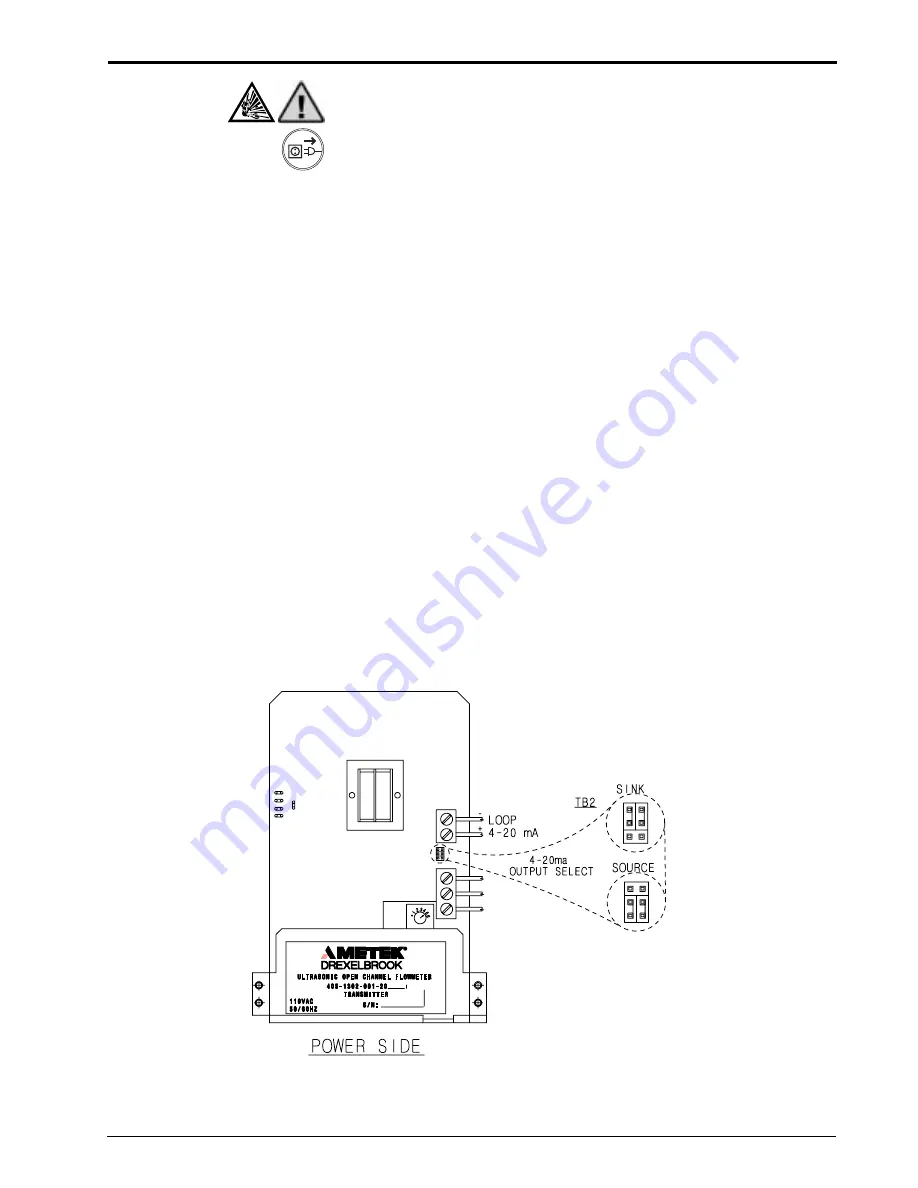
The 505-1302 is shipped with the Output Select jumper
block set to
Source
output (the instrument supplies 24 Vdc
power to the signal loop). If an external power supply is
used, the jumper should be moved to
Sink
output position.
See
Figure 2-3
for an example of a loop wiring diagram.
•••••
For loop wiring, it is recommended to use twisted, shielded
pair to eliminate noise. The shield or drain wire should be
grounded at the power supply end and left floating at the
ultrasonic transmitter end.
Figure 2-3
Output Select Jumper
Содержание Drexelbrook 505-1320 Series
Страница 4: ......
Страница 6: ......
Страница 20: ...14 505 1320 Series Ultrasonic Open Channel FlowmeterTM Figure 4 1 Flow and Relay Switches...
Страница 38: ......
Страница 39: ......


