background image


20


098-0010 Rev C 


Содержание MediQA

Страница 1: ...agnostic Guide AmeriWater The Water Purification Specialists 3345 Stop 8 Rd Dayton OH 45414 800 535 5585 www ameriwater com 098 0010 Rev C Manufactured With Pride in The USA MediQA Reverse Osmosis System ...

Страница 2: ......

Страница 3: ... Electrical Mechanical Faults 47 8 Component Failures 49 9 Instruction for Use IFU 50 9 1 Instructions for Adjusting Pressure Relief Valve on MediQA 50 9 2 IFU 98 9078A Updating Mitsubishi FX3G PLC Software with the FX3G EEPROM 32L Module 51 9 3 IFU 98 9160A Updating MediQA HMI Software with Jump Drive 54 9 4 IFU 98 9084B Heatsan MediQA Fill Line Disinfection 56 9 5 IFU 98 9085A MediQA Changing RO...

Страница 4: ...2 098 0010 Rev C 1 COMPONENT IDENTIFICATION 1 1 MSP Components ...

Страница 5: ...3 098 0010 Rev C ...

Страница 6: ...4 098 0010 Rev C ...

Страница 7: ...5 098 0010 Rev C 1 2 MDP Components ...

Страница 8: ...6 098 0010 Rev C ...

Страница 9: ...7 098 0010 Rev C ...

Страница 10: ...emical clean process all of the water is redirected back into the MediQA tank RECIRC PERIOD is user settable Clean The MediQA is equipped with the ability to perform a chemical cleaning of itself once chemicals have been added in the tank This mode is also displayed after Clean Recirc when the Tank drains completely then refills Clean Rinse After the clean tank drain is completed the RO will go in...

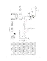
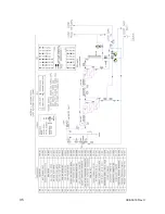
Страница 11: ...9 098 0010 Rev C 2 2 Flow Schematics 2 2 1 MSP Schematics ...

Страница 12: ...10 098 0010 Rev C ...

Страница 13: ...11 098 0010 Rev C ...

Страница 14: ...12 098 0010 Rev C ...

Страница 15: ...13 098 0010 Rev C ...

Страница 16: ...14 098 0010 Rev C ...

Страница 17: ...15 098 0010 Rev C ...

Страница 18: ...16 098 0010 Rev C ...

Страница 19: ...17 098 0010 Rev C ...

Страница 20: ...18 098 0010 Rev C ...

Страница 21: ...19 098 0010 Rev C ...

Страница 22: ...20 098 0010 Rev C ...

Страница 23: ...21 098 0010 Rev C ...

Страница 24: ...22 098 0010 Rev C ...

Страница 25: ...23 098 0010 Rev C 2 2 2 MDP Schematics ...

Страница 26: ...24 098 0010 Rev C ...

Страница 27: ...25 098 0010 Rev C ...

Страница 28: ...26 098 0010 Rev C ...

Страница 29: ...27 098 0010 Rev C ...

Страница 30: ...28 098 0010 Rev C ...

Страница 31: ...29 098 0010 Rev C ...

Страница 32: ...30 098 0010 Rev C ...

Страница 33: ...31 098 0010 Rev C ...

Страница 34: ...32 098 0010 Rev C ...

Страница 35: ...33 098 0010 Rev C ...

Страница 36: ...34 098 0010 Rev C ...

Страница 37: ...35 098 0010 Rev C ...

Страница 38: ...0 Heater Heater on Heater off X11 High Pressure Switch Stage 2 MDP only Pressure normal Pressure exceeds set point X12 Delivery High Pressure Switch Pressure normal Pressure exceeds set point X13 Permeate Divert Valve Close Limit Valve open to loop Valve closed to loop X14 Remote Standby Override Key Switch Remotely disabling RO Heat Disinfect Normal X15 Heatsan Cool Heatsan is in Cool Down Normal...

Страница 39: ...oncentrate Divert Valve Concentrate to drain Concentrate recirculating Y13 Spare Y14 Standby Customer Interlock voltage free indicates standby mode Normal Y15 Fault Normal Fault Y16 Service In normal operation Normal Y17 Heatsan In RO Heat Disinfect Normal Y20 Request Run Relay In Supply Mode also the master output to turn the slave RO on Normal Y21 Loop Return Divert Valve Drain Valve redirecting...

Страница 40: ...ed LRV Loop Return Valve Open to return loop water to tank Open to return loop water to tank Open to return loop water to tank CDV Concentrate Divert Valve Open to tank Open to tank Open to drain periodically as temperature drops Operation for Chemical Clean Ball Valve Recirculation Tank Drain High Press Rinse Low Press Rinse PSC Product to Loop Valve Closed Closed Closed Closed LRV Loop Return Va...

Страница 41: ...ank Draw Off Period Cool Down Period Open Open to Return Line on Heatsan Open to drain Standby or System Off Drain in Operation Closed Closed Open to tank Note The MediQA system uses a series of automated 2 and 3 way stainless steel valves to direct the water flow through the unit during each of the various stages of operation These valves are marked with yellow indicators that represent the openi...

Страница 42: ...e switch faulty 1 Check valve status 2 Perform chemical clean 3 Adjust the pressure switch until alarm clears 4 Replace pressure switch on stage 2 pump outlet RO1 Pump Fault Alarm Stage 1 Pump communicating fault condition X1 on 1 Check and inspect pump RO1 2 Check X1 is lit on PLC 3 Check if pump breaker is turned off 4 Check that there is no shorts between power and ground 1 Reset pump breaker 2...

Страница 43: ...on pressed on front of control panel X0 off 1 Check if E stop button on control panel is pushed in 1 Pull out E stop button on the Control Panel 2 Reset E stop on touch screen PLC Analogue Card Error Alarm PLC Analog Card communicating fault condition 1 Analog Expansion Card detected failure of Card 1 Replace Expansion Card PLC to PCB Comms Error Alarm Communication port where conductivity board c...

Страница 44: ...water issue 5 Remove and rinse diffuser Output Quality Rinse Alarm Output Quality exceeds the Output Quality Alarm Set point after the Auto Rinse Max time is met 1 Check Auto Rinse Max and Output Quality Alarm set points 2 Check Output Conductivity value 3 Loop supply quality over range 999 displayed on screen 4 Loop supply line cell error 1 Raise Auto Rinse Max 2 Profile membranes 3 Check line ce...

Страница 45: ... water supply and valves 3 Check tank drain valve is closed 4 Verify inlet solenoid valve is working 5 Check strength of flow 6 Check if diffuser is plugged 1 Open closed valve on feed 2 Close tank drain valve 3 Replace inlet solenoid 4 Address feed water issue 5 Remove and rinse diffuser Level Sensor Error Warning Float switches operated out of sequence 1 Check PLC for X6 High Level X5 Mid Level ...

Страница 46: ...Cell Error Warning Output Conductivity Sensor transmitting over the maximum detectable value for 30 seconds 1 Check sensor and wiring 2 Check conductivity board 3 Check cables between board and PLC 1 Check line cell 2 Perform chemical clean Tank Quality Warning Tank Quality Warning Set point Exceeded 1 Check Tank Quality Warning set point 2 Check conductivity with Myron l meter 3 Check water softe...

Страница 47: ... off 1 Check the controller to validate that output Y4 has fired 2 Check input X10 3 Check contactor for closure 1 Replace contactor as necessary Loop Return Valve Position Warning In operation the Loop Return Valve is not sending close limit after 30 seconds X22 on Y21 off 1 Check the controller to validate that output Y21 has fired 2 Check input X22 3 Check valve for closure 1 Replace valve as n...

Страница 48: ...onnect expansion board 2 Connect adapter cable 3 Replace adapter cable Temperature Rise Warning After 30 minutes tank temperature is lower than previous reading during RO Heat Disinfection 1 Check sensor and wiring 2 Check temperature card for power and wiring 3 Check if heater breaker is tripped 1 Correct wiring 2 Flip the breaker on Temperature Hold Low Warning Tank Temperature Probe reading is ...

Страница 49: ...e incoming water supply has been cut off or has reduced pressure 3 If fitted an external pre treatment filter may have become blocked 4 The reverse osmosis membrane may have become blocked or fouled 5 The incoming feed water supply temperature has dropped significantly 6 One of the internal pressure sustaining valves may be incorrectly set or at fault 1 Check for any displayed warning or alarm mes...

Страница 50: ...ation 1 Check any installed wires from installation 2 Check the micro switch on the softener carbon heads 3 Perform electrical testing to determine location of short The unit is in Refresh mode and won t come out of it Incoming water temperature is higher than Loop Over Temp Warning set point 1 Check set point and compare to incoming water temperature 1 Raise set point not higher than alarm set po...

Страница 51: ...49 098 0010 Rev C 8 COMPONENT FAILURES ...

Страница 52: ...lve on the Product Recovery Kit PRK to 80 psi To adjust the pressure relief valve loosen the locking nut and use a wrench to turn the bolt on the bottom of the valve 3 Now that the loop is back pressured the pressure relief valve on the MediQA can be set Adjust the MediQA pressure relief valve to 75 psi 4 The PRK pressure relief valve can now be set back to 25 psi Tighten the locking nuts on both ...

Страница 53: ...at the PLC Power Status LED is OFF 4 Place the PLC RUN STOP switch in the STOP position 5 Remove plastic cover from expansion board on the PLC 6 Gently install the FX3G EEPROM 32L module into the Optional Equipment Connector 7 With the electrical panel door open turn the panel power ON 8 Verify that the PLC Power Status LED is ON 9 Verify the PLC Run Status LED is OFF 10 Raise the FX3G EEPROM 32L ...

Страница 54: ...ftware version matches the version upgrade documentation NAMES AND FUNCTIONS OF PARTS PLC 1 PLC Power Status LED Illuminated green while power is on the PLC 2 PLC Run Status LED Illuminated green while the PLC is running 3 RUN STOP switch Starts or stops PLC code execution 4 Optional Equipment Connector FX3G EEPROM 32L module connection point FX3G EEPROM 32L module 3 4 1 2 ...

Страница 55: ...53 098 0010 Rev C 1 Front Cover Can be used to remove module from PLC 2 WR Pushbutton Initiates module writing to PLC 3 WR LED Writing indicator 1 3 2 ...

Страница 56: ...oaded onto it and plug it into the USB slot on the Pro Face HMI 2 Disconnect the black cable that attaches the Pro Face HMI to the PLC Wait about 1 minute for the PLC response timed out error on the HMI 3 There are three buttons on the right side of the error text string press the button that looks like a black box window 4 Another window will open up below the error window that shows some more bu...

Страница 57: ...d push the back button in the bottom right corner of the screen Select back again and then exit 9 A message will ask to restart the system select yes 10 When the HMI reboots the new program will be loaded Pull the USB jump drive out of the USB port and store for backup 11 Plug the communication cable from the HMI back into the port on the PLC 12 Confirm the software version by navigating CALIBRATI...

Страница 58: ...oth sides of the Heatsan fill line to isolate it from the MediQA Heatsan system The CPC couplings have a check valve feature on the male components to prevent water from traveling through them The male component is threaded into both the MediQA and Heatsan and the female side is connected directly to the Heatsan fill line thus the only water that will exit the system at this point is that water wh...

Страница 59: ...solution During filling lightly shake the tubing occasionally to release trapped air 5 Discard any unused cleaning solution 6 Allow cleaning solution to dwell in tubing for at least 15 minutes to disinfect 7 Drain the cleaning solution out of the fill line tubing 8 Rinse the line of any residual cleaning solution by filling the line with water and subsequently draining it Repeat the rinse at least...

Страница 60: ...ys before the warning is tripped in the system The following procedure describes how the value can be modified so it does not create nuisance warnings REQUIRED ITEMS The value for RO Clean Reminder is a setting in the HMI so no tools are required PROCEDURE FOR CHANGING RO CLEAN REMINDER ON HMI 1 Start from Main Menu If you are not on the Main Menu Screen then Press the Main Menu button on the Bott...

Страница 61: ...59 098 0010 Rev C 3 Enter 5555 on the Keypad and press ENT The following Screen will come up 4 Press button marked RO CLEAN 5 This Screen Appears for Setting the RO Chemical Cleaning Parameters ...

Страница 62: ...the Upper Right Hand Corner of the Screen marked Clean Reminder IN _____ Days 7 Press the number inside the box it calls up the Keypad for Changing the Value 8 Set the value on the Keypad to the Desired Setting Needs to be in a Range of 0 999 ...

Страница 63: ... ENT on the Keypad after setting the New Value 10 The Clean Reminder has been changed and the Warning will not be activated until the Left _____ Days reaches a value of 0 11 A max setting of 999 days is approximately 2 75 years ...

Страница 64: ...s been mixed recirculate the cleaning solution through the vessels In general it is a good idea to minimize the amount of permeation that occurs in the system during the recirculation and rinsing steps However do not completely stop the permeate as doing so may result in a backpressure on the membrane which can cause delamination Recirculation should approximate 35 gpm and 60 psi per vessel though...

Страница 65: ...ed and rinsed an application of AmeriClean A for inorganic scale and metals is necessary AmeriClean A is mixed at a ratio of 1 lb 266 ml of powder for every 10 gallons of clean water Proceed with the cleaning using the AmeriClean A mixture according to the above instructions for AmeriClean B Never mix AmeriClean B with AmeriClean A For more information tips and technical information regarding memb...

Страница 66: ...bar will pop up at the bottom of the screen There will be 3 boxes on this bar select the black one 4 Another small bar will pop up below the first one select offline 5 Offline mode will be entered In this mode a clock can be seen in the bottom right hand corner of the screen Touch the clock 6 Once the clock is selected the time can be adjusted Match the time to the current time The time will be in...

Отзывы: