background image

   M965985 (11/18)

4

ELECTRICAL INSTALLATION

Product

Page

PWRX Power Kit 

(PK00.WRK)

4

Plug-In AC Power Kit (PK00.PAC)

5

Hard-Wired AC Power Kit (PK00.HAC)

5

Multi-AC Power Kit (PK00.MAC)

5

Important: All faucets with the standard CR-P2 battery 

come  preaseambled from the factory. No further action 

necessary.

A


PWRX 10 YEAR BATTERY 

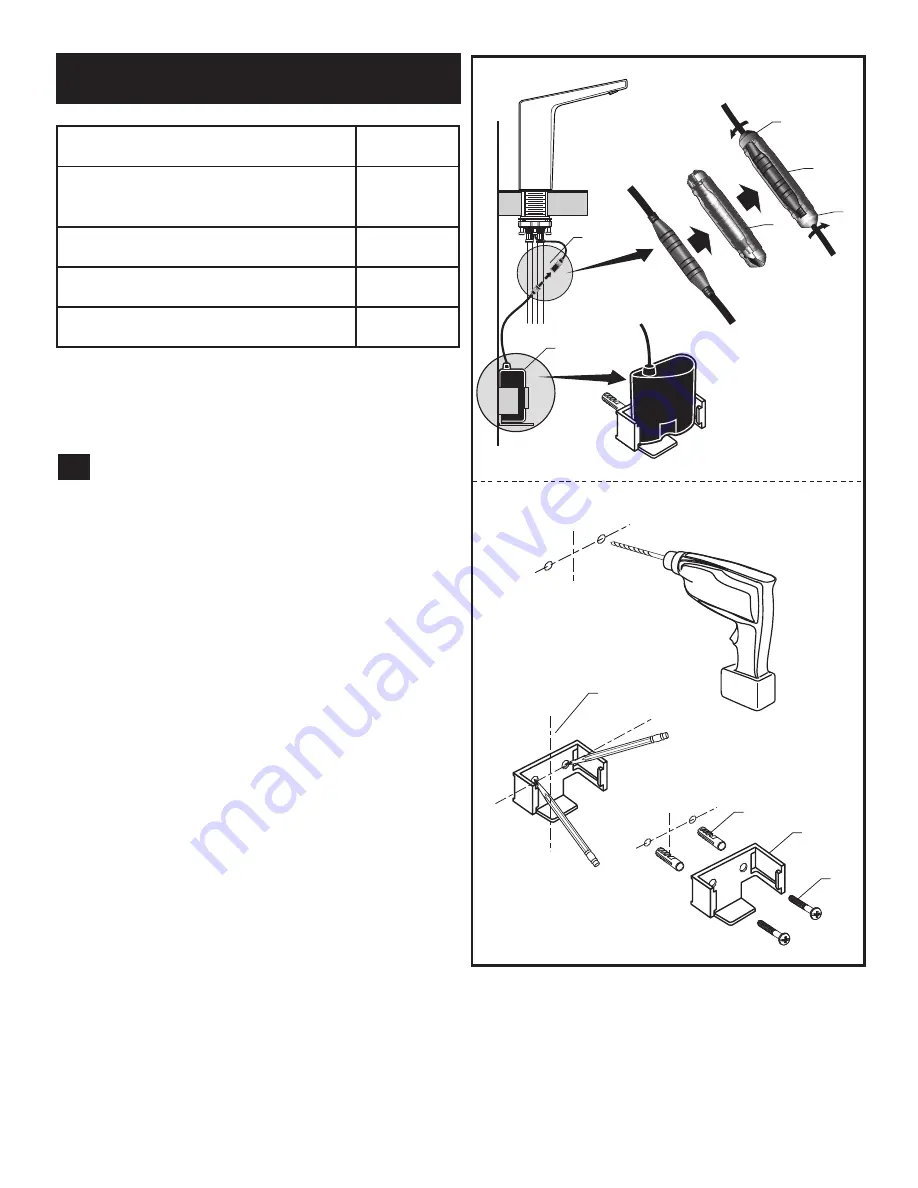
SYSTEM; Fig. 1

PWRK

 VERSION;

1.  Connect PWRX BATTERY PACK (1) to SENSOR  

CABLE 

(2).

2.  Secure the connections by installing into CONNECTOR 

LOCKING DEVICE 

(3) as shown. Rotate the END CAPS 

(4) to secure the connection within the CONNECTOR 

LOCKING DEVICE 

(3).

3.  Determine the mounting location of the PWRX BATTERY 

PACK 

(1) by marking center lines as shown.

4.  Place the BRACKET (5) on the horizontal center line 

and mark the location of the mounting holes to be  drilled.

5.  Using 1/4" diameter drill bit, drill two mounting holes     

aproximately 1" deep.

6.  Install the two ANCHORS (6) provided into the  mounting 

holes.

7.  Place the BRACKET (5) over the ANCHORS (6)  

and  secure with the SCREWS 

(7) provided.      

Do not overtighten.

8.  Insert PWRX BATTERY PACK (1) into BRACKET (5).

7

6

5

VERTICAL

C/L

HORIZONTAL

C/L

1

BRACKET INSTALLATION

Fig. 1

1

3

2

3

4

4

Содержание Paradigm Selectronic 7025.1 Series

Страница 1: ... other Assistance please call 844 CRT TEAM 844 278 8326 In Canada 1 800 387 0369 In Toronto Area only 1 905 306 1093 Paradigm Selectronic Integrated Faucet with Optional Above Deck Mixing SmarTherm MODEL NUMBERS 7025 1xx 702B 1xx 7025 2xx 702B 2xx 7025 3xx 702B 3xx CAUTION Use only American Standard supplied transformers and cable sets Using non AS supplied cables or cutting splicing or modifying ...

Страница 2: ...MAC PK00 BBU Battery Back Up Kit 7 POWER KITS SOLD SEPARATELY 702P 400 Paradigm 4 605XTMV1070 4 Mixing Valve 3 6 1 1 2018 AS America Inc Ins t al l at i on Inst ruction s 2018 AS America Inc NOTE TO INSTALLER Please give this manual to the customer after installation To learn more about American Standard Selectronic Products visit our website at www americanstandard us com or e mail us at CRTTEAM ...

Страница 3: ...n 2 If installing DECK PLATE 2 optional Apply a bead of putty to bottom edge of PUTTY PLATE 2 Install SCREW 11 into the MOUNTING BASE OF THE FAUCET 13 and allign SCREW 11 with HOLE 12 3 Insert SUPPLY HOSES 3 SHANK 4 and SENSOR CABLE 5 only included in base model through hole in DECK PLATE with PUTTY PLATE 2 and mounting surface 4 Assemble RUBBER WASHER 7 BRASS WASHER 8 and THREADED LOCKNUT 9 onto ...

Страница 4: ...CE 3 as shown Rotate the END CAPS 4 to secure the connection within the CONNECTOR LOCKING DEVICE 3 3 Determine the mounting location of the PWRX BATTERY PACK 1 by marking center lines as shown 4 Place the BRACKET 5 on the horizontal center line and mark the location of the mounting holes to be drilled 5 Using 1 4 diameter drill bit drill two mounting holes aproximately 1 deep 6 Install the two ANC...

Страница 5: ...sets Using non AS supplied cables or cutting splicing or modifying any components will void the warranty B AC VERSIONS HARD WIRED PLUG IN POWER SUPPLY Fig 2 Important Turn off power to outlet or electrical box FOR PLUG IN VERSION 1 Connect PLUG IN AC POWER SUPPLY 2 to one end of the SINGLE AC ADAPTER 6 2 Connect SENSOR CABLE 4 to the other end of the SINGLE AC ADAPTER 6 3 Connect PLUG IN AC POWER ...

Страница 6: ...emoving the handle preset the desired water temperature and while disassembling make sure to keep the SHAFT EXTENSION 8 in place 1 Unthread SET SCREW 3 and remove HANDLE 5 2 Remove LIMIT STOP 1 3 Using a Slotted screwdriver unthread SCREW 7 and remove SHAFT EXTENSION 8 Note Hold the extension in place while unthreading the screw 4 Install CAP 9 onto the Body and press until you hear a click Note S...

Страница 7: ...t COVER 15 off 2 Disconnect SENSOR CABLES 6 and 7 from the BATTERY and SOLENOID VALVE Fig 9 3 Push BATTERY 17 forward and Pull it out Fig 8 4 Replace the new battery with the same placement Insert terminal side first C CHANGE SENSOR RANGE Fig 8 9 1 Remove 3 COVER SCREWS 1 2 Remove the COVER 15 3 Disconnect the BLACK POWER SUPPLY CONNECTOR 7 and reconnect Fig 9 4 While the SENSOR CONTROL LED 9 is b...

Страница 8: ... 4 WARNING Do not turn the THERMO VALVE 4 More than 1 turn The maximum mixed water temperature can not be increased due to ASSE 1070 requirements E GENERAL CLEANING 1 Only use a damp soft cloth to clean the spout and the sensor 2 For tougher dirt use a soft cloth with diluted dish washing detergent Wipe the area using a wet cloth and dry using a soft cloth CAUTION Do not scratch the sensor when cl...

Страница 9: ...XTERNAL SUPPLY STOPS CRITICALLY LOW BATTERY INSTALL NEW BATTERY DEAD BATTERY INSTALL NEW BATTERY REPEAT NO CHECK FOR DAMAGE TO SENSOR WIRE INSULATION REPLACE SENSOR ARE EXTERNAL SUPPLY STOPS OPEN REPEATED DOUBLE FLASH ON SENSOR RECONNECT BATTERY TO SENSOR DOES SENSOR FLASH FOR 5 SECONDS REPLACE SOLENOID YES YES NO CHECK FOR DAMAGE TO SENSOR WIRE INSULATION REPLACE SENSOR RECONNECT BATTERY TO SENSO...

Отзывы: