background image

MegaRAC® G4 User’s Guide 

12 

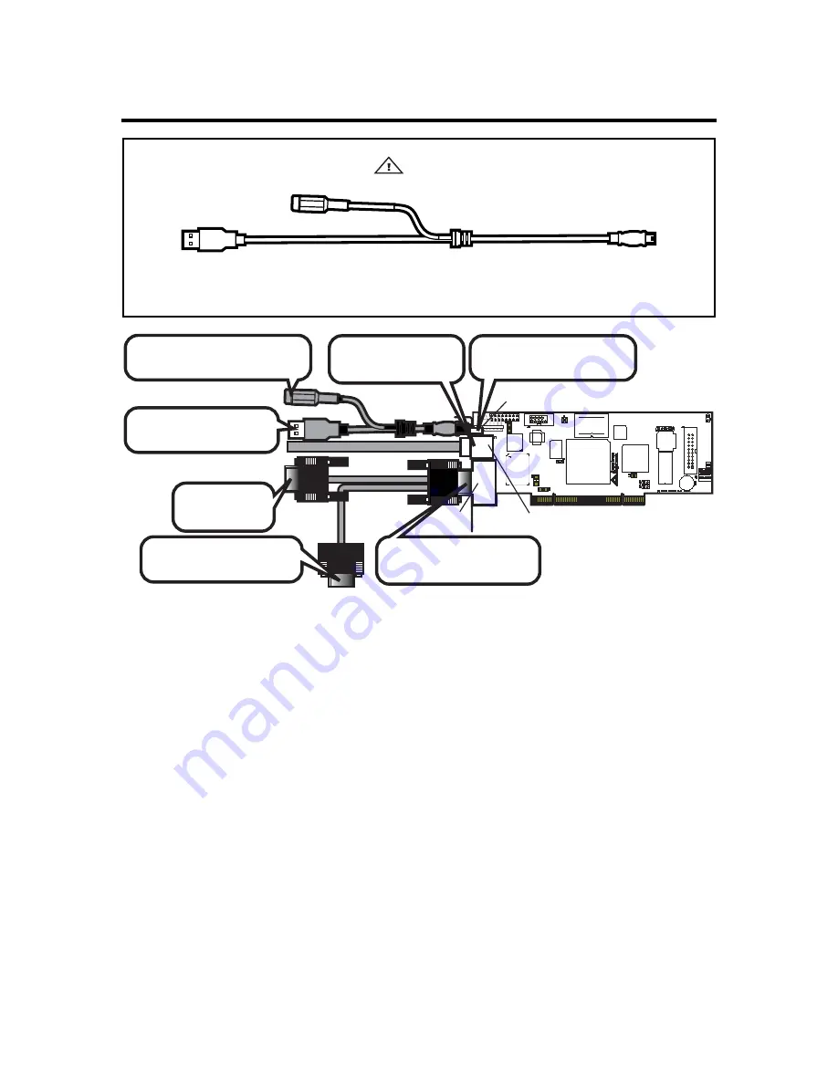
J6 USB In, J7 Network and J8 VGA In External Connectors 


Warning


The MegaRAC G4 USB Cable is specifically designed for the MegaRAC G4, revision E PCB and newer 

revisions only. Do not use the MegaRAC G4 USB Cable for any other MegaRAC device. 


Connect the MegaRAC G4
USB cable to the card.

(Optional) Connect the Power 
Adapter to the card.

Connect to the USB Port
on the Host System.

Connect to the VGA port 
on the Host System.

Connect the VGA Splitter 
Cable to the card.

Connect to the 
local Monitor.

Connect the Network 
Cable to the card.

USB In

Network

VGA In


Note:


The MegaRAC G4 USB Cable is not drawn to scale. 
 

Note:


The AC Adapter (optional) continues to provide power to the MegaRAC card in the event 
that the host system is on standby mode (3.3V STB) or powered on. 
 

Содержание MegaRAC G4

Страница 1: ...MegaRAC G4 User s Guide MAN 940 01 04 07 ...

Страница 2: ...f the Intel Corporation MS DOS and Microsoft are registered trademarks of the Microsoft Corporation Microsoft Windows is a trademark of the Microsoft Corporation IBM AT VGA PS 2 and OS 2 are registered trademarks and XT and CGA are trademarks of the International Business Machines Corporation Other trademarks and trade names may be used in this document to refer to either the entities claiming the...

Страница 3: ...p 4 Confirm the Motherboard s BIOS Settings 7 Step 5 Initial Configuration of the MegaRAC G4 card 8 G4ConfigApp 8 Intel Device Spy for UPnP Technologies 9 Setup your Client System s Internet Browser 10 Step 6 Install Boot to an Operating System 10 Chapter 3 MegaRAC G4 Card Layout 11 J1 JTAG Joint Test Action Group ICE In Circuit Emulator Connector 11 J2 J3 and J4 Not Used 11 J5 Recovery Configurat...

Страница 4: ...ard 31 Mouse 32 Options 32 Device 33 Help 33 Power Status and Control 33 Maintenance Group 33 Firmware Update 34 Logging Out 34 Appendix A Troubleshooting 35 BMC Not Responding 35 Problem 35 Symptom 35 Solution 35 Cannot Power On the Host System Remotely 36 Problem 36 Symptom 36 Solution 36 Appendix B Serial Over LAN 37 Hardware Setup 37 BIOS 37 Connecting using Hyper Terminal 37 Appendix C G4Conf...

Страница 5: ... 47 How to login 47 Display the list of targets one can work with 47 How to get the target list under another target from CDT 47 Changing the Current Default Target 48 How to get help 48 How to check values of sensors or targets 48 How to set the values of the sensor or targets 48 Using advanced options 49 A ll option 49 L evel option 49 E xamine option 49 Display option 49 Format option 49 Wildca...

Страница 6: ...cts purchased directly from AMI or from an AMI authorized reseller only If Then You purchased this product from AMI or from a certified AMI reseller Call AMI technical support at 770 246 8645 Please be prepared to specify the serial number of the product This AMI product was installed as part of a system manufactured by a company other than AMI or you purchased an AMI product from an unauthorized ...

Страница 7: ...cation as is without warranty of any kind either expressed or implied including but not limited to the implied warranties of merchantability or fitness for a specific purpose Some states do not allow disclaimer of express or implied warranties or the limitation or exclusion of liability for indirect special exemplary incidental or consequential damages in certain transactions therefore this statem...

Страница 8: ... Optional Warning The MegaRAC G4 USB Cable is specifically designed for the MegaRAC G4 revision E PCB and newer revisions only Do not use the MegaRAC G4 USB Cable for any other MegaRAC device Note The AC Adapter optional continues to provide power to the MegaRAC card in the event that the host system is on standby mode 3 3V STB or powered on The AC Adapter plugs into the MegaRAC G4 USB Cable Note ...

Страница 9: ...ay cause harmful interference to radio communications Operation of this device in a residential area is likely to cause harmful interference in which case the user will be required to correct the interference at his own expense If this equipment does cause harmful interference to radio or television reception which can be determined by turning the equipment off and on the user is encouraged to try...

Страница 10: ...se A répond à toutes les exigences de l interférence canadienne causant des règlements d équipement L opération est sujette aux deux conditions suivantes 1 ce dispositif peut ne pas causer l interférence nocive et 2 ce dispositif doit accepter n importe quelle interférence reçue y compris l interférence qui peut causer l opération peu désirée European Communities Electromagnetic Compatibility EMC ...

Страница 11: ... screen frame updates even with 16 bit color Up to 1280 X 1024 resolution support KVM IP console redirection Analog VGA input AMI s AVICA2a Analog fourth generation algorithm High performance up to 30 frames per second 1280x1024 1280x960 1152x864 1024x768 800x600 640x480 Extremely low network band width requirement Auto session timeout for security Local pass through output to monitor using splitt...

Страница 12: ... Directory and Open LDAP support Client application to extend the LDAP schema easily SMASH and CLP support IPMI 2 0 boot option support Telnet based SOL Power control of the server Fully compliant with the DMTF specification Multilanguage support Full Unicode support Multiple language support for multiple clients simultaneously Web based configuration Full configuration using web UI Personality mi...

Страница 13: ...tic mat Wear an anti static wristband grounded at the same point as the anti static mat You can also use a sheet of conductive aluminum foil grounded through a one megaohm resistor instead of the anti static mat Similarly a strip of conductive aluminum foil wrapped around the wrist and grounded through a one megaohm resistor serves the same purpose as a wristband Hardware Installation Use the foll...

Страница 14: ... jumper is installed pins one and two open J16 J17 Verify that these two headers are each shorted with a jumper If J16 and J17 are not shorted short pins one and two on both J16 and J17 Note J14 and J15 can be used in place of the MegaRAC Feature Cable to gather I2C bus information from the motherboard MegaRAC G4 Card Layout USB In Network VGA In J10 RS232 Serial Port J5 Recovery Configuration J18...

Страница 15: ...anel of the Host System Reset Switch Cable Runs between the MegaRAC G4 and the Reset Header located on the Host System s Motherboard I2C Cable Optional with Limitations Runs between the MegaRAC G4 and the IPMB Header located on the Host System s Motherboard To the Monitor 15 pin Female To the MegaRAC G4 15 pin Female To the Host System s VGA Port 15 pin Male MegaRAC Feature Connector Cable not to ...

Страница 16: ...Cable J18 MegaRAC Feature Connector Connect the MegaRAC Feature cable from the motherboard to the card Optional Connect this cable to motherboard s IPMI IPMB I2C connector Connect this cable to the motherboard Power On pins Connect this cable to the motherboard Reset pins Connect the cable from the chassis Power Switch to these pins Connect the cable from the chassis Reset Switch to these pins Ins...

Страница 17: ...e The AC adapter is an optional component Note The AC Adapter optional continues to provide power to the MegaRAC card in the event that the host system is on standby mode 3 3V STB or powered on Step 4 Confirm the Motherboard s BIOS Settings Power on the motherboard and enter the BIOS Using the following table confirm that your motherboard s BIOS settings are correct BIOS Section Setting Boot Optio...

Страница 18: ... out its IP Address you can run either Intel Device Spy for UPnP Technologies or use the G4ConfigApp Utility located on your CD G4ConfigApp The MegaRAC card can be located using the G4ConfigApp utility Once the IP Address is located or configured you can use your Internet browser to access the MegaRAC card remotely The G4ConfigApp utility is a GUI based program that must be run from the host machi...

Страница 19: ...sal Control Point UCP This tool readily tests action invocations and events Device Spy also traces packets sent to UPnP devices For more information on how to use Intel Device Spy for UPnP Technologies see the documentation provided with it Step Action 1 Download the Intel Device Spy for UPnP Technologies program onto your remote client system Run the Intel Device Spy for UPnP Technologies program...

Страница 20: ...ing signed by VeriSign so that they could be authenticated by Internet browsers If redirection does not operate properly you may have to set up Internet Explorer s Security Settings to allow the downloading of Unsigned ActiveX controls and also allow it to run Unsigned ActiveX controls as well Step 6 Install Boot to an Operating System At this stage if you already have an operating system loaded o...

Страница 21: ...ctor not mounted This header is used to debug and service the MegaRAC G4 card J1 is not described in this document J2 J3 and J4 Not Used Do not use these headers if you have a MegaRAC G4 Revision E As of Revision E these headers are no longer active and in the future will not be mounted on the PCB J5 Recovery Configuration Mode Jumper J5 Recovery Configuration Verify that this jumper is not shorte...

Страница 22: ...SB cable to the card Optional Connect the Power Adapter to the card Connect to the USB Port on the Host System Connect to the VGA port on the Host System Connect the VGA Splitter Cable to the card Connect to the local Monitor Connect the Network Cable to the card USB In Network VGA In Note The MegaRAC G4 USB Cable is not drawn to scale Note The AC Adapter optional continues to provide power to the...

Страница 23: ...al Port Optional Connect the Serial Cable from the motherboard to the card You can connect an external 9 pin serial port connector to this header This header is primarily used to text redirect over the serial port J11 and J12 Not Used Do not use these headers if you have a MegaRAC G4 Revision E As of Revision E these headers are no longer active and in the future will not be mounted on the PCB ...

Страница 24: ...us means that there is no physical connection between the two I2C pins on the PCI slot and the motherboard s I2C bus Shorting J14 and J15 would be useless in this case Note J14 and J15 can be used in place of the MegaRAC Feature Cable to gather I2C bus information from the motherboard Note Only the OEM version can utilize the hardware health monitoring capabilities of MegaRAC G4 card The hardware ...

Страница 25: ...t switch functionality Power On Cable Reset Switch Cable I2C Cable MegaRAC Feature Connector Cable J18 MegaRAC Feature Connector Connect the MegaRAC Feature cable from the motherboard to the card Optional Connect this cable to motherboard s IPMI IPMB I2C connector Connect this cable to the motherboard Power On pins Connect this cable to the motherboard Reset pins Connect the cable from the chassis...

Страница 26: ...therboard power and reset switch It can also be used to gather I2C bus information from the motherboard Pin Description Pin Description 1 Not Connected 11 Reset_Host 2 I2C Clock 12 Ground 3 Not Connected 13 Cable Detect 4 Not Connected 14 Ground 5 Power_Off 15 3 3V 6 I2C Data 16 Ground 7 5V PCI 17 3 3V 8 3V SB 18 Ground 9 5V PCI 19 PCI Reset 10 3V SB 20 Ground Note J14 and J15 can be used in place...

Страница 27: ...nagement Bus IPMB and Intelligent Chassis Management Bus ICMB The IPMI specification defines the interface between management software and chassis management hardware The IPMB specification defines the internal Intelligent Platform Management Bus The ICMB specification defines an external bus for connecting additional IPMI enabled systems The electrical interconnect for system management is based ...

Страница 28: ...MegaRAC G4 User s Guide 18 ...

Страница 29: ...function is described in detail Note Your MegaRAC G4 GUI may not match this document If it does not appear to be the same you can visit ami com and download the most current user s guide Default User Name and Password When you first try to access your MegaRAC G4 you will be prompted to enter a user name and password The default user name and password are as follows Field Default User Name root Pas...

Страница 30: ...oups General Information Group Server Health Group Configuration Group Remote Control Group Maintenance Group General Information Group This group of pages allows you to view system information System Information This page displays information about the firmware and device availability Server Health Group This group of pages allows you to view the sensor readings system event logs and allows confi...

Страница 31: ...being monitored by an external BMC you will need to provide the slave address so that the MegaRAC G4 card will be able to read data from the onboard BMC on the motherboard server board 0x20 is the address most commonly used PMCP monitoring file sp bin Select the Soft Processor SP File with the BIN file extension Sensor definitions file sdr dat Select the SDR File with the BIN file extension Upload...

Страница 32: ...All Sensors Temperature Sensors Voltage Sensors Fan Sensors Sensor Readings This field displays the individual sensor s name reading and the current status of the sensor Refresh Button Use this button to refresh the sensor readings view Show Thresholds Button Clicking Show Thresholds button expands the sensor reading table and also show the various threshold settings for every sensor Name Status R...

Страница 33: ...view and modify the network settings on this page Select whether to obtain an IP address automatically or manually configure one Item Description MAC Address This field displays the MAC address of the MegaRAC G4 card Obtain an IP address automatically use DHCP This option allows the MegaRAC G4 s IP to be configured by a DHCP server dynamically Use the following IP address This option allows you to...

Страница 34: ...sociation with the User Name User Name This field displays a list of all users who are able to access this MegaRAC G4 Note The default administrator is root It is prudent for you to change the root password Network Privilege This field displays the network rights associated with the account Add User Button Use this button to add a new user You must select an open field first Modify User Button Use...

Страница 35: ...he Username field Your user name must be at least four characters long and no more than 32 characters long User names are case sensitive and must start with an alphabetical character Password Enter a password in the Password field Your password must be at least eight characters long Note The password must be a minimum of eight characters and a maximum of 32 characters Use a mixture of alphanumeric...

Страница 36: ...ote The password must be a minimum of eight characters and a maximum of 32 characters Use a mixture of alphanumeric and special characters for better security The password is case sensitive Confirm Password Confirm your password by entering your password again in the Confirm Password field Network Privileges Assign network permissions and access rights Administrator Operator User Callback No Acces...

Страница 37: ...d alert entry Modify Button Use this button to add a new alert configuration entry or modify an existing one Send Test Alert Button Use this button to test the selected alert configuration entry Alert Modify Alert Please enter the information for the new alert below and press Save Item Description Event Severity You select the severity of the event that you want to trigger an alert Disable All Inf...

Страница 38: ...e this button to make the settings active SSL Configuration Here you can upload an SSL Certificate and SSL Private Key to use when accessing your MegaRAC G4 Item Description Default Certificate This field displays the Default Certificate Default Private Key This field displays the Default Private Key New SSL Certificate This field allows you to upload an SSL Certificate and SSL Private Key Browse ...

Страница 39: ...l always know who is accessing network resources and can easily define user group based policies to control access Use the following fields to authenticate and access the LDAP server Item Description Enable LDAP Authentication Check this box to enable LDAP authentication through an LDAP server Port Enter the port address of your LDAP server A common port used by LDAP is port 389 IP Address Type in...

Страница 40: ... MegaRAC G4 is the ability to redirect the host system s console To redirect the host system s console is the ability to manage your host system as if it were physically in front of you when it is not The following table is a list of basic keystrokes and their functions Keystroke Description ATL S Start Console Redirection ATL T Stop Console Redirection ATL R Restart Console Redirection ATL F Togg...

Страница 41: ... Keyboard This dropdown menu contains the following dropdown menu items Menu Item Description Hold Right Ctrl Key This menu item can be used to act as the right side CTRL key when in Console Redirection Hold Right Alt Key This menu item can be used to act as the right side ALT key when in Console Redirection Hold Left Ctrl Key This menu item can be used to act as the left side CTRL key when in Con...

Страница 42: ...eed and quality is that more speed tries to reduce the data over network and thus reducing quality and vice versa Video Settings The Video Performance Parameters allows you to enhance the frame rate of your remote console session Red Gain slider This slider allows you to increase or decrease the amount of red Green Gain slider This slider allows you to increase or decrease the amount of green Blue...

Страница 43: ...st system Select one of the options listed in the following table to execute on your host system You will be asked to confirm your choice Upon confirmation the command will be executed and you will be informed of the status Item Description Select Power Control Mechanism Dropdown Menu Select the power control mechanism option You can select one of the following types Using External IPMI BMC via IP...

Страница 44: ...ternet browser and log back onto the MegaRAC card before you can perform any other types of operations You can update the device s firmware here Select the Enter Update Mode button to put the device in a special mode that allows firmware update You can now follow the instructions presented in the subsequent pages to successfully update the card s firmware The device will reset if update is cancele...

Страница 45: ...user cannot get the sensor information In order to make the BMC come out of that state the system needs to be rebooted The BMC s I2C address should never be set to 0x21 that is not a valid address 0x20 is the correct address for almost all BMCs If it is not the BMC or motherboard provider must supply the correct one Many BMCs feature a reset button that can be used to reset the BMC only That butto...

Страница 46: ...cted to the MegaRAC G4 remotely using the GUI power on power off and power cycle does not work properly Solution The user should make sure that the feature cable is connected properly from the G4 card and the host system s main board and chassis The wall AC adapter must be connected to the MegaRAC G4 card in order for power control options to operate properly ...

Страница 47: ...ccess Configurations menu 4 Set the Remote Access setting to Serial 5 Set the Serial Port Number to COM1 or COM2 depending on the serial COM port you are using 6 Set the Serial Port Mode baud rate you desire By default it is set to 19200 8 n 1 7 If available you can set the Post Boot Support option When enabled the MegaRAC G4 attempts to output the DOS screens or the initial windows text screens T...

Страница 48: ...MegaRAC G4 User s Guide 38 ...

Страница 49: ... to change the way the MegaRAC G4 card connects to the network By default the MegaRAC G4 card obtains an IP address dynamically via DHCP You can change this by specifying the IP address network mask and gateway The Network Configuration fields are explained below Field Button Description MAC Address The MAC Address field displays the current MAC and PHY unique hardware address Configuration Method...

Страница 50: ...u can use this field to enter the account password Note The password must be a minimum of eight characters and a maximum of 32 characters Use a mixture of alphanumeric and special characters for better security Confirm Password You must reenter the password The Confirm Password field allows you to reenter the user s password Permissions You can select the permission level for this account User Pro...

Страница 51: ...ed into the MegaRAC G4 card s serial port connector at J10 Once the external 9 pin serial port connector is installed and secured to the chassis attach the null modem cable BIOS After you have established a physical connection from your host system s serial port to you MegaRAC G4 card you must enable Remote Access in your AMIBIOS Step Description 1 From the host system s terminal enter the AMIBIOS...

Страница 52: ...ow to use Hyper Terminal Usage of Hyper Terminal is therefore not documented here Remember What Connect using the Serial Port either COM1 or COM2 Bits per second set to 19200 Data bits set to 8 Parity set to None Stop bits set to 1 Flow control set to None Note To invoke the DEL key map the DEL key to the BACKSPACE key in the Hyper Terminal Properties window ...

Страница 53: ...Note When you log in using the default root user name and password you have full administrative powers It is advised that once you log in you change the default root password You will be able to use the SMASH commands once you are logged in Applicable Documents and References SM_CLP Specification SM Addressing Specification SM Managed Element Profile Specification IPMI specification SM Architectur...

Страница 54: ...es it much easier to manage servers regardless of the vendor It does away with a lot of time spent searching through manuals to figure out how to do different tasks on the various servers in the data center The reason SMASH is so simple and so straightforward is found on an earlier DMTF project the Common Information Model CIM which is now built into most existing servers SMASH leverages the richn...

Страница 55: ...he profiles and specific MAP implementation dump PROFILE Move a binary image from the MAP to a URI exit MUST Used to terminate a CLP session help MUST Used to get context sensitive help The functionality is the same as the help option with the addition of help for targets load PROFILE Move a binary image to the MAP from a URI reset PROFILE Used to cause a target with power process control to cycle...

Страница 56: ...stem which is marked by a number As per SMASH CLP specification a target is comprised of UFcT UFsT where UFcT signifies the string part and the UFsT signifies the number The system can contain targets such as cpu nic sensors etc The complete list of targets may be found in the SMASH CLP BNF Smash will work for targets that it can discover from SDR SEL and FRU files There are some hard coded target...

Страница 57: ... In G3 from the command prompt one has to type SMASH and the SMASH CLP prompt will come forth Display the list of targets one can work with The following command will enlist the targets that SMASH CLP will support Æ show display targets This command will show the targets in the current default target CDT This means that if we in folder then the above command will show the targets under root If we ...

Страница 58: ...gets The command to use is show and then we have to associate a target and the property with it Æ show sensor1 This will show the values associated with the sensor1 To see one particular value of the target we have to use the property keyword for the command Æ show display properties IP nic1 To see one or more properties for a particular target we can use multiple properties Æ show display propert...

Страница 59: ...tion will not execute the command but only say if the command given is ok or not Æ cd examine system1 Display option The display option is used to display the properties of targets If display is associated with all then it shows all the properties of the target Format option The format option specifies the output format of the commands The formats are plain text default clpxml clpcsv clpkeyword Æ ...

Страница 60: ...MegaRAC G4 User s Guide 50 ...

Страница 61: ... to the MegaRAC G4 card 5120 TCP CD Redirection iUSB CD Bi directional Data sent from the MegaRAC G4 card to the client as well as from the client to the MegaRAC G4 card 5123 TCP Floppy Redirection iUSB Floppy Not used in newer firmware 7578 TCP Video Redirection Bi directional Data sent from the MegaRAC G4 card to the client as well as from the client to the MegaRAC G4 card 3072 UDP Trap out port...

Страница 62: ...MegaRAC G4 User s Guide 52 ...

Страница 63: ...Appendix F MAC Address Map 53 Appendix F MAC Address Map MAC Address Location Description 00 40 D9 02 9B 3C Server Room Rack 2 5 Windows 2003 Advanced Server Mail Server ...

Страница 64: ...MegaRAC G4 User s Guide 54 Notes ...

Страница 65: ...G General Information Group 20 H Hardware Installation 3 Hardware Setup 37 41 Help 33 How to check values of sensors or targets 48 How to get help 48 How to get the target list under another target from CDT 47 How to login 47 How to set the values of the sensor or targets 48 I Installing Your MegaRAC G4 Card 3 Introduction 1 44 Introduction 44 IPMB Intelligent Platform Management Bus 17 J J1 JTAG ...

Страница 66: ... your Client System s Internet Browser 10 SMASH CLP Architecture 44 SMASH Command Line Utility 41 Solution 35 36 SSL Configuration 28 Step 1 Unpack the MegaRAC G4 card and check jumper settings 4 Step 2 Plug in the MegaRAC G4 card into the Host System and Attach Internal Cables 5 Step 3 Connect External Cables 7 Step 4 Confirm the Motherboard s BIOS Settings 7 Step 5 Initial Configuration of the M...

Отзывы: