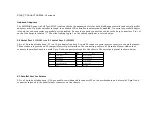
Step 5 Connect the Power Supply,
Continued
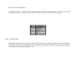
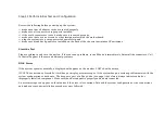
See the following figure for the location of connectors P2 and P3. AT-compatible power supplies have two 6-pin connectors that
are inserted in P2 and P3. The 6-pin connector with 3 red wires and 2 black wires is connected to P3 and the remaining 6-pin
connector is connected to P2.
Содержание 42 Series
Страница 1: ...American Megatrends Inc Series 42 Mark V Baby Screamer 80386 Motherboard User s Guide ...
Страница 2: ...MAN 642 Rev C 9 11 92 ...
Страница 13: ......
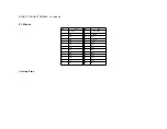
Страница 35: ...A29 SA02 B29 5 A30 SA01 B30 OSC A31 SA00 B31 GND ...
Страница 59: ......
Страница 82: ......
Страница 85: ...SRAM Locations ...
Страница 89: ...Installing Adapter Cards 26 27 ...

