background image

 AMERICAN-LINCOLN

1-37

SC7730

DUST CONTROL

KNOB

DUST CONTROL

PANEL FILTER

Fig. 57

Fig. 58

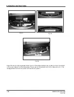
DUST CONTROL KNOB

The dust control knob is used to hold the dust control filter cover down as shown in figure 57. The dust control
filter is located under the front cover and will need to be removed periodically for cleaning or replacement.
Removal of the filter panel requires no tools.  The front cover must be opened to gain access to the filter
compartment.  The panel filter is held in place by a hinged frame and knob. To remove the panel filter, turn the
knob counterclockwise and lift the hinged frame. The panel filter can now be lifted out and cleaned or replaced.
To install the replacement panel filter, place a new filter in the machine, lower the frame and twist the knob
clockwise to lock the filter in place.

FILL WITH

HYDRAULIC FLUID

CHECK FLUID LEVEL

HYDRAULIC RESERVOIR FLUID LEVEL SIGHT GAUGE

The fluid level sight gauge is located on the right side of the machine under the front cover as shown in figure 59.
The sight gauge is used to indicate the level of fluid in the reservoir.  The fluid level must be visible in the sight
gauge when the hopper is in the down position.

Fig. 59

OPERATING INSTRUCTIONS

Содержание SC7730

Страница 1: ...hine READ THIS BOOK This book has important information for the use and safe operation of this machine Failure to read this book prior to operating or attempting any service or maintenance procedure to your machine could result in injury to you or to other personnel damage to the machine or to other property could occur as well you must have training in the operation of this machine before using i...

Страница 2: ...1 2 AMERICAN LINCOLN SC7730 ...

Страница 3: ...STMENT KNOBS 1 25 SOLUTION FLOW KNOB 1 26 HORN BUTTON 1 26 FOOT PEDAL PARKING BRAKE 1 27 SEAT POSITION ADJUSTMENT 1 28 SEAT SAFETY FEATURES 1 28 D DISCLAIMER 1 4 M MACHINE PREPARATION 1 13 MACHINE SPECIFICATIONS 1 10 O OPERATING INSTRUCTIONS 1 29 PRE START CHECKLIST 1 29 FILLING SOLUTION TANK 1 29 STARTING MACHINE 1 30 TRANSPORTING MACHINE 1 30 THE CLEANING OPERATION 1 30 STANDARD ESP SCRUBBING SY...

Страница 4: ...ny way or in the event that such machinery or controls are not maintained in a proper manner the instructional material contained herein may be rendered inaccurate The information contained herein is to be used only by persons knowledgeable in the operation of machinery such as that described herein or other persons being directly supervised by such knowledgeable persons No portion of this manual ...

Страница 5: ...he model number catalog number and serial number when ordering 2 Give the part number description and quantity of parts needed 3 Give shipping instructions for either freight UPS or parcel post Parts and supplies listed in this manual can be ordered from the following address 1 Use the model number catalog number and serial number when ordering 2 Give the part number description and quantity of pa...

Страница 6: ...ush Hazard Cover or Hopper Could Close Turn Key Off Lock Wheel WARNING ATTENTION Squeegee Up Vacuum Off Battery Charger Choke Fan On Filter Shaker On Forward Reverse Headlights Hopper Dump Hopper Return Horn Main Broom Side Broom Up Main Broom Side Broom Down No Step Off On Power Recovery Tank High Scrub Brush Down On Scrub Brush Up and Off THESE SYMBOLS IDENTIFY CONTROLS DISPLAYS FEATURES AND SAF...

Страница 7: ...horized personnel only WARNING The following safety labels are mounted on the machine in the locations indicated If the labels become damaged or illegible replace with identical label Scrub deck presents hazard for crushing entanglement friction and abrasion Dust Control Motor presents hazard for shearing and cutting Broom Chamber presents hazard for entanglement friction and abrasion ...

Страница 8: ...ories may get caught in the machine and cause physical injury Wear OSHA NIOSH protective eye wear or prescription glasses to protect eyes Wear appropriate gloves when filling and or draining tanks Before operating machine test brake mechanism lights and back up alarm if applicable Observe maintenance schedule guidelines to assume optimal safe operation of the machine Be aware of pinch pints that e...

Страница 9: ...ntrate recommended by the chemical manufacturer Water solutions or cleaning materials used can leave wet areas on floor surfaces causing dangerous conditions for the operator or other persons Always put CAUTION signs near area you are cleaning Use care when reversing machine Always empty the solution tank and recovery tank before doing maintenance Unplug the battery first to prevent possible injur...

Страница 10: ... U Turn 87 in 221 cm DIMENSIONS Length 87 in 221 cm Width 46 in 116 8 cm Height 52 in 132 cm Height w Overhead Guard 79 in 200 6 cm Wheel Base 37 6 in 95 5 cm WEIGHT Standard Machine Battery 1700 lbs 765 kg without battery 720 Ah battery 1990 lbs 896 kg TIRES Front Battery Solid Urethane Two 2 16 in 41cm x 3 75 in 8 26 cm Rear Battery Solid Rubber One 1 16 in 41 cm x 4 00 in 10 16cm RAMP CLIMBING ...

Страница 11: ...ac 46 in 116 8 cm Swing break away w no tool squeegee replacement Side 26 in 66 cm Easy Change TANKS Solution Tank 55 Gallons 208 liter Polyethylene RecoveryTank 55 Gallons 208liter Polyethylene Solution Metering Variable to 3 0 GPM 11 4 lpm Drain Hose 48 in 122 cm Clean Out Port 5 7 in 14 5 cm heavy debris HOPPER Capacity 2 5 cu ft 71liter DUMP AND LIFT Dump Height 14 in 35 6 cm SYSTEM FLUID CAPA...

Страница 12: ...1 12 AMERICAN LINCOLN SC7730 SPECIFICATIONS ...

Страница 13: ...tempt to operate without reading the following instructions UNPACKINGANDASSEMBLING MACHINE The SC7730 is shipped on a pallet and held in place with wooden block to stop the machine from moving 1 Remove wooden blocks holding machine in place 2 Position a 11 and 48 ramp on base of pallet 11 DEGREE 48 INCHES Fig 2 Fig 1 ...

Страница 14: ...od up and pull the battery lever up to the right Use a battery lifting device with a 2000 LB 907KG capacity to place the battery into the battery tray Push battery lever down to the left to lock the battery into place Plug the battery power connector into the machine power connector Lower the hood into place 5 Charge battery as shown in the manual Read battery manufacturer literature for battery c...

Страница 15: ...er to the right 3 Lower the battery into place using a 2000 LB 907 KG capacity lifting device 4 Rotate the battery lever to the left to lock the battery into place 5 Connect battery wires according to manufacturer s direction 6 Connect the battery power connector to the machine power connector 7 Lower the machine front cover into place WARNING Do not leave charged batteries on concrete surface the...

Страница 16: ...tch 5 ESP switch 6 Spray Vac Wand switch 7 Scrub brush switch 8 Squeegee switch 9 Main side broom switch 10 Filter shaker Dust control switch 11 Hopper switch 12 Battery condition meter Hour meter 13 Circuit breakers 14 Solution flow knob 15 Parking Brake 16 Steering wheel adjustment lever 17 Foot throttle 18 Forward Reverse switch 19 Key switch 20 Horn Figure 9 ...

Страница 17: ...d accessories KEY SWITCH CONTROLS Figure 10 Figure 11 FORWARD REVERSE SWITCH FORWARD REVERSE SWITCH The forward reverse switch is located on the operator s console as shown in figure 11 Pressing the upper half of the forward reverse switch will result in the machine moving forward when the foot throttle is depressed Pressing lower half of the forward reverse lever switch will result in the machine...

Страница 18: ...e when maintenance should be done on the machine HOUR METER Figure 12 Figure 13 CONTROLS BATTERY CONDITION METER BATTERYCONDITION METER The battery condition meter is located on the instrument panel as shown in figure 12 The condition meter indicates the level of charge in the batteries The batteries are sufficiently charged when all of the LED s are illuminated amber as shown on the ramp illustra...

Страница 19: ... the lower half of the switch the headlights and taillights will be activated Pressing the upper half of the switch will turn off the lights HOPPER INDICATOR LIGHT HOPPER OPEN WARNING LIGHT The hopper open light switch is located on the instrument panel as shown in figure 15 When the hopper is open the light is illuminated the broom and the dust control fan will stop Figure 15 ...

Страница 20: ...o 30 seconds Releasing the switch returns to the off position The dust control fan will stop when the filter shaker has been activated The filter shaker will only operate with the hopper in the DOWN position DUST CONTROL SWITCH The dust control switch is located on the instrument panel as shown in figure 17 To turn on the dust control system for normal sweeping press the lower half of the switch W...

Страница 21: ...automatically when the machine moves forward or reverse SQUEEGEE SWITCH The squeegee switch is located on the the instrument panel as shown in figure 19 Pressing the lower half of the switch lowers the squeegee and activates the squeegee vacuum Pressing the upper half of the switch will turn off the squeegee vacuum and raise the squeegee In the middle position the switch will raise the squeegee In...

Страница 22: ...lution warning light illuminates when the solution tank is empty marking the end of the scrubbing cycle HIGH RECOVERY LIGHT The high recovery warning light is located on the instrument panel as shown in figure 21 The light will illuminate approximately 5 minutes before the recovery tank is full giving ample time to complete the scrubbing cycle before the mechanical float shuts off the vacuum to th...

Страница 23: ...s in and hold the upper half of the switch until the hopper closes completely then release WARNING To prevent the hopper from closing while doing maintenance lock the hopper in the open position into place with the safety arm Figure 22 CONTROLS MAIN BROOM Figure 23 SIDE BROOM and MAIN BROOM SWITCH The side broom and main broom switch is located on the instrument panel as shown in figure 23 By pres...

Страница 24: ...ight is illuminated Clean the recovery tank when the tank is emptied NOTE Do not place clean water in the recovery tank when using ESP option the solution tank could become overfilled during operation ESP Figure 24 Figure 25 CONTROLS SPRAY AND VAC WAND SWITCH Optional The spray and vac wand switch is located on the instrument panel as shown in figure 24 Pressing the bottom half of switch turns on ...

Страница 25: ... right of the dust control filter as shown in figure 27 Turning the knob to the left counterclockwise will lower the main broom CONTROLS Figure 27 Figure 26 SIDE BROOM ADJUSTMENT The side broom adjustment knob for changing the sweep height to compensate for broom wear is located in front of the machine to the right of the dust control filter as shown in figure 26 Turning the knob to the left count...

Страница 26: ...er the flow of water and solution will be Turning the knob counterclockwise will decrease the flow of the water and solution To turn the water and solution off turn the knob all the way counterclockwise NOTE For best results discontinue application of solution 10 feet before stopping or making a 90 or 180 turn HORN BUTTON HORN BUTTON The horn button is located on the instrument panel as shown in f...

Страница 27: ...direction and then press down on the foot throttle to move set the machine in motion Increase the foot pressure to increase the travel speed Figure 30 BRAKE PEDAL PEDAL LOCK PARKING BRAKE The parking brake is located on the floor of the machine left of the foot throttle as shown in figure 31 To set the parking brake press down on the foot pedal and the press down the lock To unlock the parking bra...

Страница 28: ...ft and move the seat to the desired position and then release the lever to lock the seat into place Figure 34 SAFETYFEATURES SEAT SAFETY SWITCH Machine will not move and parking brake will set if this switch is not activated SPEED INTERLOCK Maximum machine speed will be reduced while scrub brushes are in use BRUSHES OFF IN NEUTRAL Scrub brushes automatically disengage when machine is idle AUTOMATI...

Страница 29: ...ck hydraulic fluid level Check hydraulic connections for leaks Check brakes and controls for proper operation Check broom pattern Check to ensure that all covers panels and access doors are securely closed SOLUTION TANK Figure 35 TO FILL SOLUTION TANK Open the solution lid located on the top left side of the machine as shown in figure 36 Fill tank with 55 gallons of water and the correct mixture o...

Страница 30: ... squeegees are in the up or raised position with all other controls in the off position 2 Release the parking brake 3 Push the forward reverse switch to desired position up for forward and down for reverse 4 Push down on the foot throttle to obtain desired travel speed 5 Release the foot throttle to slow down or stop when on a flat surface To slow the machine when decending down an inclined surfac...

Страница 31: ...ecovery tank to the solution tank Fig 40 OPERATING INSTRUCTIONS SOLUTION TANK RECOVERY TANK STRAINER SCRUB BRUSH SQUEEGEE FLOOR CONTACT SOLUTION CONTROL VALVE SOLUTION CONTROL VALVE THE NON RECYCLING OR STANDARD SCRUBBING MODE During the scrubbing process detergent solution water from the solution tank is fed to the solution line There it is fed to the floor where three disc scrubbing brushes work...

Страница 32: ...el to sharply when machine is in motion The machine is very responsive to movement of the steering wheel so avoid sudden turns Try to follow as straight a path as possible Avoid bumping into posts or scraping the sides of the machine When placing the machine in motion avoid slamming the directional control pedal all the way forward suddenly This is equivalent to starting out in HIGH and puts needl...

Страница 33: ...d place in a suitable floor drain as shown in figure 42 Open the drain hose plug as shown in figure 43 and 44 IMPORTANT Improper discharge of wastewater will damage the environment and is illegal The U S Environmental Protection Agency has established certain regulations regarding discharge of wastewater The local city and state regulations regarding wastewater discharge may be in effect in your a...

Страница 34: ...he draining operation is complete open the recovery tank clean out door as shown in figure 46 and flush the recovery drain hose as shown in figure 47 Clean the recovery tank and recovery tank screen as shown in figure 48 Close the recovery tank clean out door drain hose plug the recovery tank lid and clip the drain hose into place as shown in figure 49 Fig 46 Fig 47 Fig 48 Fig 49 OPERATING INSTRUC...

Страница 35: ... 53 Inspect the disk scrub brushes and replace when the bristles are reduced to 3 4 inch length as shown in figure 50 and 51 Inspect the main and side brooms When the bristles are worn to 1 5 inches in length replace the main broom as shown in figure 52 Replace the side broom when bristles are worn to 3 5 inches as shown in figure 53 ...

Страница 36: ... SIDE SQUEEGEE Fig 54 Fig 55 Fig 56 Inspect the rear and side squeegee blades for wear If the wiping edge becomes rounded remove and reinstall so the unworn edge is now the wiping edge This process can be repeated until all four edges are worn If the squeegee blade has become rippled it will need to be replaced ...

Страница 37: ...nd knob To remove the panel filter turn the knob counterclockwise and lift the hinged frame The panel filter can now be lifted out and cleaned or replaced To install the replacement panel filter place a new filter in the machine lower the frame and twist the knob clockwise to lock the filter in place FILL WITH HYDRAULIC FLUID CHECK FLUID LEVEL HYDRAULIC RESERVOIR FLUID LEVEL SIGHT GAUGE The fluid ...

Страница 38: ...1 38 AMERICAN LINCOLN SC7730 American Lincoln Printed in USA ...

Отзывы: