


SpeedDome Ultra III Camera Dome
8000-2573-01, Rev. B
INSTALLATION AND SERVICE GUIDE
13
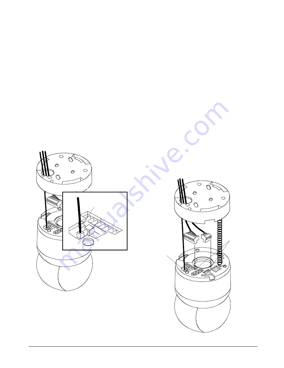
3. Connect video cable to mini BNC in top of
housing and eyeball assembly (Figure 12).
Press BNCs together. A firm snap indicates a
tight connection.
4. If dome is connected at end of comm. line,
set termination jumper JW1 (Figure 12).
Jumper JW1 is pre-installed across pins 1–2
(unterminated). These pins are closest to the 9-
pin connector. If dome is to be connected at the
end of a communications line, place jumper
across pins 2–3 (terminated).
You may need a small slotted screwdriver to
gently pry jumper loose. Be careful not the
damage the underlying PC board.
Figure 12. Video cable connection and
termination jumper location
5. Connect 9-pin and 4-pin plugs to top of
housing and eyeball assembly (Figure 13).
CAUTION:
DO NOT connect 9-pin plug unless
you have performed step 3 first!
6. Check LEDs to verify that power and data
are reaching dome (Figure 13).
LEDs CR2, CR3, and CR4 surround video
connection and are visible through opening.
LEDs light in the following order:
1. Green CR2 LED blinks indicating data
present (RS422 or SensorNet).
Yellow CR4 LED glows steadily indicating
communication between controller and
dome (RS422), or glows steadily, turns off,
and then blinks (SensorNet).
2. Red CR3 LED blinks slowly indicating that
dome software is operating.
Note:
To check RS422 connections, set
dome address switch SW3 to 9 and check
red and green LEDs. Red should be off,
green should blink. If red blinks, RS422 is
wired backwards. If red and green are off,
there is no RS422 communication. When
done with this test, set switch SW3 back to 0
and reset dome from controller.
Figure 13. 9-pin and 4-pin cable connections
Video
Connection
Termination
Jumper
LEDs CR2,
CR3, and CR4
visible through
opening.
Pin 1


