background image

14

Pilot Tube Air Flow Balancing - Commercial

It is necessary to have balanced air flows in an HRV. The volume of
air brought in from the outside must equal the volume of air exhausted
by the unit. If the air flows are not properly balanced, then;

The HRV may not operate at its maximum efficiency

A negative or positive air pressure may occur
in the building

The unit may not defrost properly

Failure to balance HRV properly may void warranty

Excessive positive pressure may drive moist indoor air into the ex-
ternal walls of the building where it may condense (in cold weather)
and degrade structural components. May also cause key holes to
freeze up.

Excessive negative pressure may have several undesirable effects.
In some geographic locations, soil gases such as methane and ra-
don gas may be drawn into the building through basement/ground
contact areas. Excessive negative pressure may also cause the
backdrafting of vented combustion equipment.

Read the Application Warning on the front of this manual!

Prior to balancing, ensure that:

1.

All sealing of the ductwork system has been completed.

2.

All of the HRV’s components are in place and functioning properly.

3.

Balancing dampers are fully open.

4.

Unit is on HIGH speed.

5.

Air flows in branch lines to specific areas of the house should

be adjusted first prior to balancing the unit. A smoke pencil used
at the grilles is a good indicator of each branch line’s relative air
flow.

6.

After taking readings of both the stale air to the HRV duct and

fresh air to the house duct, the duct with the lower CFM ([L/s]
velocity) reading should be left alone, while the duct with the
higher reading should be dampered back to match the lower
reading.

7.

Return unit to appropriate fan speed for normal operation

BALANCING PROCEDURE

The following is a method of field balancing an HRV using a Pitot
tube, advantageous in situations when flow stations are not installed
in the ductwork. Procedure should be performed with the HRV on
high speed.

The first step is to operate all
mechanical systems on high
speed, which have an influence
on the ventilation system, i.e. the
HRV itself and the forced air fur-
nace or air handler if applicable.
This will provide the maximum
pressure that the HRV will need
to overcome, and allow for a
more accurate balance of the
unit.

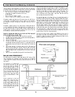
Drill a small hole in the duct
(about 3/16"), three feet down-
stream of any elbows or bends,
and one foot upstream of any el-
bows or bends. These are rec-
ommended distances but the
actual installation may limit the
amount of straight duct.

The Pitot tube should be connected to a magnehelic gauge or other
manometer capable of reading from 0 to 0.25 in. (0-62 Pa) of water,
preferably to 3 digits of resolution. The tube coming out of the top of
the pitot is connected to the high pressure side of the gauge. The
tube coming out of the side of the pitot is connected to the low pres-
sure or reference side of the gauge.  

I

nsert the Pitot tube into the

duct; pointing the tip into the airflow.

For general balancing it is sufficient to move the pitot tube around in
the duct and take an average or typical reading. Repeat this proce-
dure in the other (supply or return) duct. Determine which duct has
the highest airflow (highest reading on the gauge). Then damper that
airflow back to match the lower reading from the other duct. The
flows should now be balanced.  Actual airflow can be determined
from the gauge reading. The value read on the gauge is called the
velocity pressure. The Pitot tube comes with a chart that will give the
air flow velocity based on the velocity pressure indicated by the gauge.
This velocity will be in either feet per minute or meters per second.
To determine the actual airflow, the velocity is multiplied by the cross
sectional area of the duct being measured.

The accuracy of the air flow reading will be affected by how close to
any elbows or bends the readings are taken. Accuracy can be in-
creased by taking an average of multiple readings as outlined in the
literature supplied with the Pitot tube.

Содержание 1500 SFDE

Страница 1: ...l failure may result in the backdrafting or improper function ing of vented combustion equipment TO BE COMPLETED BY CONTRACTOR AFTER INSTALLATION ___________________________________________________________________ Installing Contractor ___________________________________________________________________ Telephone Contact ___________________________________________________________________ Serial Num...

Страница 2: ...s being exhausted These instructions are intended as a general guide and do not supercede local codes in any way Con sult authorities who have jurisdiction before install ing INTRODUCTION TABLE OF CONTENTS Cover Installation Information 1 General 2 Engineering Data 3 4 Function and Controls 5 Additional Features 6 Servicing 7 Mounting the 1500 8 Roof CurbAssembly Instructions 9 Roof Curb Detail 10...

Страница 3: ...s with 1 2 O D drain connections MOUNTING Unit to be set on support brackets hung by threaded rod type apparatus Brackets and rod not included CONTROLS FUNCTION Integrated microprocessor circuit board 3 independently adjustable motor speeds WEIGHT 480 lbs 218 kg SHIPPING WEIGHT 525 lbs 238 kg Engineering Data Model HRV 1500 SFD DIMENSIONS 1500SFD inches A B C D E F G H I J L SFD 18 2 5 18 12 37 66...

Страница 4: ...oated steel insulated 1 thick Elastomeric insulation DRAIN Two powder coated galvanized steel drain pans with 1 2 O D drain connections MOUNTING Rooftop mounted on optional roof curb Part No 28 125 CONTROLS FUNCTION Integrated microprocessor circuit board 3 independently adjustable motor speeds WEIGHT 480 lbs 218 kg SHIPPING WEIGHT 525 lbs 238 kg DIMENSIONS 1500SFDE inches A B C D E F G H I J K L ...

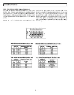
Страница 5: ...he designated speed taps A jumper wire is factory installed in the low speed position Note It is recommended to use the optional speed control Part 28 895 in order to obtain full fan speed control Optional Speed Control Part 28 885 Micro Processor Board Optional Remote Dehumidistat Part 28 882 Boosts unit to high speed when humidity is higher than setpoint Optional DVC Control Part 28 883 Same as ...

Страница 6: ... desired airflow This is done on the ECM circuit board located within the Additional Features electrical box Both motors contain a separate ECM circuit board to allow for independent adjustment of the motors The adjust tap will change the airflows on all three of the speeds Please note that this unit has been factory set to obtain 1500CFM at 1 w g external static pressure Adjust ment of the high s...

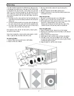
Страница 7: ...in access to either side of the unit Servicing Filters 1 Remove filter service panel one or both sides 2 Remove first set of filters 3 Remove filter divider panels if only accessing from one side 4 Remove filters from behind filter divider panel 5 Replace all filters Ensure that filter divider panels are reinserted into unit Servicing Cores 1 Remove core service panel one or both sides 2 Slide cor...

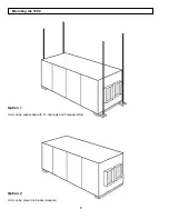
Страница 8: ...8 Option 1 Unit can be suspended with U channels and Threaded Rod Mounting the 1500 Option 2 Unit can be placed on blocks sleepers ...

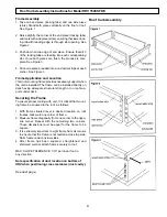
Страница 9: ...having adequate structural strength or on roof sup ports under deck Securing the Frame To ensure proper mating with unit it is critical that mount ing frame be squared to the roof as follows 1 With frame situated level in desired location on roof trusses tack weld one corner of frame 2 Measure frame diagonally from one corner to the oppo site corner Repeat with the remaining two corners These dime...

Страница 10: ...10 Roof Curb Detail for Model HRV 1500 SFDE ...

Страница 11: ...uires exterior hoods to be provided by the contractor NOTE It is extremely important to design and install the fresh air intake in an area where the hoods will gather the freshest air free from restriction Recommended No less than 10 ft 3 m apart from each other or per local code restriction At least 18 in 46 cm above ground level Away from sources of contaminants such as automobile exhaust fumes ...

Страница 12: ...ve the contaminants while not allowing them to enter the breathing zone of the occupants For contaminants that are lighter than air grilles should be located high on the wall If contaminants are heavier than air a lower placement of the grilles will be required Information on a contaminants specific gravity and toxicity should be available from the chemical data sheets Fresh Air Supply System The ...

Страница 13: ... 1500 SFD SFDE have been programmed to provide constant airflow on each airstream for external static pres sures of up to 1 w g but at a location closer to the air handler The air handler would have a constant running blower to effectively distrib ute the fresh air and remove the stale air Balancing damp ers would be located in both the HRV supply and exhaust ducts between the return air plenum an...

Страница 14: ...n the ductwork Procedure should be performed with the HRV on high speed The first step is to operate all mechanical systems on high speed which have an influence on the ventilation system i e the HRV itself and the forced air fur nace or air handler if applicable This will provide the maximum pressure that the HRV will need to overcome and allow for a more accurate balance of the unit Drill a smal...

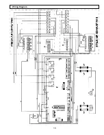
Страница 15: ...15 Wiring Diagram ...

Страница 16: ...arasota FL 941 351 3441 or fax 941 351 3442 to find the name of your nearest dealer in order to repair the product The labor required to install any replacement part s shall be dealt with at the option of the customer in either of the following ways a The customer may supply labor at their own expense or b If the product was purchased from a dealer then the dealer will supply labor at cost to the ...

Отзывы: