background image


63 

6    DISPLAY MODE 


6.1 Radar View 

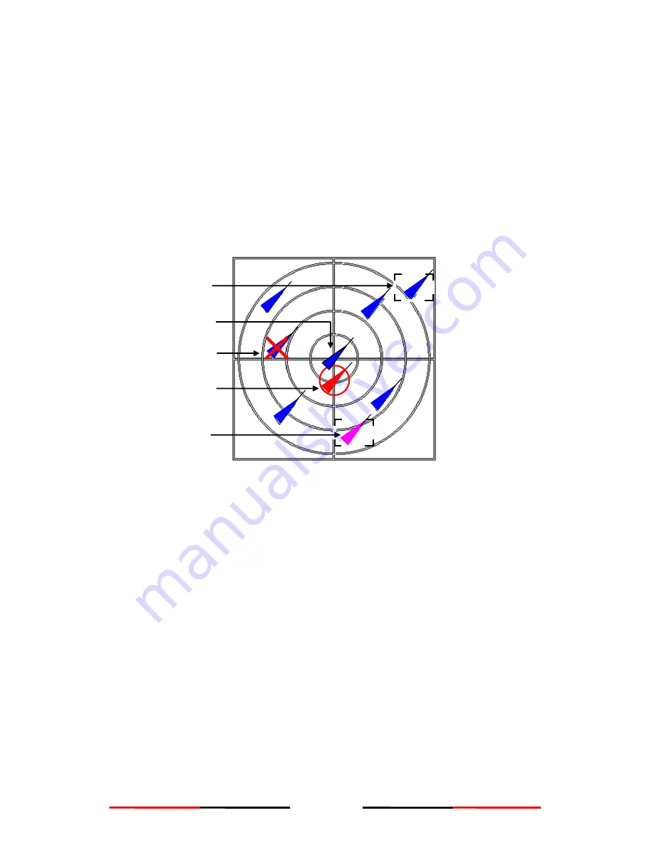
The AIS targets are displayed on your AMEC CAMINO-

201‟s screen as shown below. These 

data are generated from the AIS data received from the vessels in the surrounding sea. These 

data have various indications and are dynamic. 


Below are some characteristics of the AIS targets: 

  Each AIS target is in the shape of a triangle and represents for one ship only. 

  Under normal GPS reception, own ship is located in the center of the radar view. 

  A maximum number of 500 AIS targets can be displayed on the radar view at one time. 

  Vectors of a target can be displayed when it is an active target. The vectors are referred as 

a target‟s COG and SOG.   

  The straight line extended from AIS target represents the course of the ship. 


Figure 6-1 Radar View 

Selected Target 

Dangerous  Target 

Own  Ship 

Friend  Ship 

Lost Signal Target 

Содержание CAMINO-201

Страница 1: ...to improve our AIS products to satisfy all customers needs information in this document is subject to change without notice AMEC does not make any representations or warranties implied or otherwise re...

Страница 2: ...e proceeding to installation or operation WARNING SAFETY INSTRUCTIONS ELECTRICAL SHOCK HAZARD Do not open the case of the equipment Only qualified personnel could work on the interior of the equipment...

Страница 3: ...now you can have a better control of your surrounding sea and have an enjoyable voyage Camino 201 AIS is strictly tested to meet the rigorous demands of the marine environment Unless improper use ins...

Страница 4: ...Unit 6 2 1 3 Items in the Package 6 2 2 Installation Procedure 7 2 2 1 Installation Precautions 7 2 2 2 Step by Step Installation Instructions 8 2 2 3 Connector Pin Definition and Wiring 13 2 2 4 VHF...

Страница 5: ...Version and Information 47 5 3 Ship Configuration and Setting 48 5 3 1 Own Ship Static Data User Password Protected 48 5 3 2 Friend Ship Editing 50 5 4 Transceiver ON OFF Settings 52 5 5 System Config...

Страница 6: ...70 7 2 Dimensions 73 7 3 Accessories 75 7 4 Trouble Shooting 75 7 4 1 Problem Analysis By Status LED Indicator 75 7 4 2 Problem Analysis Hardware 76 7 4 3 Problem Analysis Software 77 8 AMEC WORLD WID...

Страница 7: ...nding area but also receive the dynamic information position speed SOG and etc static information ship name MMSI call sign and etc and voyage related information cargo type destination and etc from an...

Страница 8: ...ure of these AIS systems in navigations is different as illustrated in the following table CAMINO 201 is a Class B AIS transponder Table 1 2 Type of AIS Class A AIS Transmits and receives AIS signal i...

Страница 9: ...er called COG Speed Over Ground hereinafter called SOG Heading Dynamic Reports Speed of the ship Status of the ship SRM Alarm Safety 1 4 AIS Report Rate The CAMINO 201 supports following report rate i...

Страница 10: ...ti collision and is serves as a compliment to navigation It is not navigational equipment and does not replace any navigational system installed on board Although AIS is operated automatically by itse...

Страница 11: ...ter leaks into the equipment FOLLOW THIS INSTRUCTION MANUAL TO PROCEED WITH THE INSTALLATION AMEC and your local agent dealer will not bear any responsibility of equipment damage or personnel injury d...

Страница 12: ...1 2 Mounting bracket with buckle tenons ASM CRU AISCLB01 1 Washer ACC WHR 001 2 Spring washer ACC WHR 002 2 M8 Screws ACC SRW 001 4 NOTE 1 AMEC would not be able to fully ensure overall product perfor...

Страница 13: ...ked at 4 Installation should proceed in a safe environment and does not have direct contact with rain or splashing water 1 When installation is completed please remember to key in own ship s MMSI data...

Страница 14: ...stallation Instructions AMEC CAMINO 201 can be installed and mounted on flat surface or it can be hung on the ceiling or wall as shown below Figure 2 2 2 1 Installation overview Table Stand Mounting C...

Страница 15: ...ed to secure the mounting brackets at the 4 holes marked I Installation Instructions Step 2 1 2 3 Step 1 Place the mounting bracket on the desired spot for installing the CAMINO 201 Refer to Figure 2...

Страница 16: ...CAMINO 201 should face forward and the front edge of the mounting bracket should face down NOTE For faster and easier installation the Buckle Tenon for angle adjustment has fixed on the body joint Re...

Страница 17: ...nt as shown in Figure 2 2 2 5 Step 4 8 9 5 Step 5 Knob should be placed outside of the body joint Spring Washer and Washer should be placed outside of the body joint in the order as shown in Figure 2...

Страница 18: ...E AMEC GPS ANTENNA WITH CAMINO 201 Step 2 Step 5 Step 3 Step 1 2 4 6 5 3 Connect the GPS cable to the GPS ANT connector Connect the VHF cable to the VHF ANT connector 2 Connect other NMEA 0183 compati...

Страница 19: ...nterface cable contains 12 different wires Refer to the following table for the wiring details Table 2 2 3 2 NEMA 0183 wiring details PIN COLOR NAME FUNCTION 1 Brown RXP Positive CAMINO 201 receives e...

Страница 20: ...the following table for the wiring details Table 2 2 3 3 RS 232 wiring details RS 232 Wiring Refer to the following wiring method for the external RS 232 device with RS 232 interface NO NAME FUNCTION...

Страница 21: ...the VHF antenna location should be placed in accordance to Figure 2 2 4 Figure 2 2 4 VHF GPS Antenna Location We recommend you choose AMEC AIS VHF antenna To save space you can also choose VHF GPS com...

Страница 22: ...Antenna location We recommend you choose AMEC AIS GPS antenna To save space you can also choose VHF GPS combo antenna provided by AMEC 2 3 Antenna Cabling When connecting the cable s with the CAMINO 2...

Страница 23: ...Bluetooth Pairing Refer to the manual of your Bluetooth device for connection AMEC s default pairing security code is 0000 NMEA 0183 12V 24V DC VHF Antenna Connector M Jack GPS Antenna Connector TNC f...

Страница 24: ...by pressing the power button Step 2 After the unit is turned on the system will run a self testing as shown below Welcome to AMEC AIS System power on testing To turn on the unit press the power butto...

Страница 25: ...can only be entered ONCE as regulated A pop out window will appear to confirm this process Choose CANCEL and skip to Step 7 Choose OK and the MMSI set up screen will appear as shown in Step 5 AMEC AI...

Страница 26: ...munications Commission to input an MMSI that has not been properly assigned to the end user or to otherwise input any inaccurate data in this device Step 6 When completed entering the MMSI press the E...

Страница 27: ...t broadcast own ship s voyage related information before MMSI is set The system now can only receive other ships broadcastings For the system to be fully functioning follow the instructions in section...

Страница 28: ...Status Indication Light 4 CHANNEL 1 2 Channel 1 2 Indication Light 5 UP Arrow Key UP DOWN Arrow Key DOWN LEFT Arrow Key LEFT RIGHT Arrow Key RIGHT 6 ENT Enter Key Confirm Selection 7 SRM Safety Relat...

Страница 29: ...3 When the status indicator turns green the unit will function automatically TURNING THE POWER OFF Step 1 When the unit is ON and functioning press the power button will switch off the unit Figure 3 2...

Страница 30: ...situations resolved Red ON Power Error Check for power connection and power voltage Flash BIIT alarm An abnormal condition of the device is detected during BIIT Built In Integrity Test NOTE NOTE With...

Страница 31: ...tion D Own Ship Data E Region Setting Step 1 Press the SRM key Step 2 Use the UP and DOWN keys to select safety related message Step 3 Press the ENT key to confirm and transmit the message System will...

Страница 32: ...dynamic information Details refer to section 6 Figure 4 2 1 Radar View LAT LON GPS SOG COG HDT REG 00 00 00 00 00 00 83 05 123w 28 39 60 0n 3D 15 00Kn 96 4 10 9 160 40 00 E 167 40 00 E 90 40 00 N 90 2...

Страница 33: ...PA value this target will be considered as a dangerous target The dangerous targets will then be listed as shown below Step 1 Use the UP and DOWN keys to select a dangerous target ship Step 2 Press th...

Страница 34: ...igure 4 2 4 Own ship details SHIP DETAIL 2 2 NAME CALL MMSI CARGO TYPE DEST ETA IMO BEAM LENGTH AMEC AIS B CS N A CLASS B 000000000 DG HS OR MP POLUTANT A HSC SHANGHAI 12 31 23 59 3m DRAFT DTE 1 5m N...

Страница 35: ...region settings are broadcasting from the VTS assigning a certain channel setting in a region Step 1 Use the UP and DOWN keys to select a region setting Step 2 Press the ENT key on the selected regio...

Страница 36: ...s etc Press the DIM key to adjust the brightness of the screen To turn off the backlight Press and hold the DIM key for more than 2 seconds Press any key to turn it back on 1 2 Stepless brightness adj...

Страница 37: ...3 4 5 6 7 8 9 space 4 5 Menu Key On the main display radar view press the MENU key to enter to main menu Totally 6 main functions are available in the main menu UP and DOWN arrow keys Press the UP an...

Страница 38: ...rmation can be set and entered in the SHIP SETTING Ship s information Ship name ship size type of ship and etc Friend ship information The ship that is added as a friend ship with its MMIS and ship na...

Страница 39: ...automatically return to the main display NOTE 2 A password is required to enter in order to access and change the information of the following functions Password required to change the following setti...

Страница 40: ...INITIAL INBOX 5 1 1 OUTBOX 5 1 2 SRM 5 1 3 OWN SHIP 5 2 1 AIS TARGETS 5 2 2 REGION LIST 5 2 3 SHIP INDEX 5 2 4 VERSION 5 2 5 OWN SHIP 5 3 1 FRIEND SHIPS 5 3 2 CUSTOMIZE 5 5 1 RADAR VIEW 5 5 2 FACTORY...

Страница 41: ...and 3 sub menus will appear Step 4 Use the UP and DOWN keys to select INBOX OUTBOX and SRM 5 1 1 Inbox Received SRM Step 1 Select the INBOX function Step 2 Press the ENT key to access into the INBOX S...

Страница 42: ...selection Step 6 Select YES to delete the SRM Step 7 Select NO to cancel and return to the Inbox SRM list MMSI Maritime Mobile Service Identification DATE TIME Date and Time Received READ Read Status...

Страница 43: ...window will appear to confirm the selection Step 6 Select YES to delete the SRM Step 7 Select CANCEL to cancel and return to the outbox SRM list MESSAGE Sent Message Content DATE TIME Date and Time Se...

Страница 44: ...t the SRM Refer to table 7 1 for System preset Safety Related Message Step 4 Press the ENT key to send the selected SRM Step 5 A confirming window will appear to confirm the sending of the SRM Step 6...

Страница 45: ...ROBBERY ATTACK ENGINE TROUBLE FUEL SHORTAGE 5 2 AIS Target Status Step 1 On the main display radar view press the MENU key to open the main menu Step 2 Select the AIS STATUS function Step 3 Press the...

Страница 46: ...p s static information Step 4 Use the LEFT key to view own ship s dynamic information Step 5 The ENT key can also be used to switch between own ship s dynamic and static information SHIP DETAIL 1 2 NA...

Страница 47: ...BRG Bearing between own ship and target ships COG Course Over Ground CPA Closest Point of Approach DEST Destination ETA Estimate Time of Arrival CARGO Cargo Type EPFD Electronic Position Fixing Devic...

Страница 48: ...arget Step 4 Use the LEFT and RIGHT keys to scroll to the next and previous page in the target list Step 5 Press the ENT key to open the selected target Step 6 Use the RIGHT and LEFT keys to view targ...

Страница 49: ...Select the REGION LIST function Step 2 Press the ENT key to display the entire region setting information Step 3 Use the UP and DOWN key to select the region setting AIS STATUS OWN SHIP AIS TARGETS R...

Страница 50: ...r 07 02 08 07 Region 9 DEFAULT N A Region In Use T Zone Status Region 9 NO Region 1 e g Region 1 Message was received at Region 1 Received Date is 2007 05 26 Message was received from an AIS receiver...

Страница 51: ...Low 25K HZ 25K HZ REGION 1 SETTING LAT NE Latitude North East LON NE Longitude North East LAT SW Latitude South West LON SW Longitude South West T Zone nm Transition Zone Band Width Band width A Chann...

Страница 52: ...n the ship data display SHIP INDEX MMSI English Local 100352369 Ship name 1 XX 1 256357963 Ship name 14 XX 14 210366395 Ship name 38 XX 38 3162346395 Ship name 46 XX 46 456456963 Ship name 3 XX 3 SHIP...

Страница 53: ...system s software version and related information Step3 In the version page information such as PRODUCT FIRMWARE COMPANY WEBSITE and S N are displayed Step4 Press the ESC key to escape from this menu...

Страница 54: ...ain display radar view press the MENU key to open the main menu Step 2 Select the SHIP SETTING function Step 3 Press the ENT key on the SHIP SETTING function and 3 sub menus will appear Step 4 Use the...

Страница 55: ...Step 3 The following data can be set in the OWN SHIP function Own ship name call sign type of ship location of the GPS antenna Call sign input only 7 digitals Ship name input only 20 digitals Step 4...

Страница 56: ...d ship data select the ship and press MENU a pop out window will appear Select YES to delete the set up or NO to return to the BUDDY LIST SHIP SETTING OWN SHIP FRIEND SHIPS INDEX BUDDY LIST MMSI Engli...

Страница 57: ...ENT key to open the friend ship data BUDDY LIST MMSI English Local 100352369 Ship name 52 XX 52 256357963 Ship name 34 XX 34 310366395 Ship name 16 16 318666395 Ship name 74 74 100352369 English Ship...

Страница 58: ...N keys to turn ON or OFF the transceiver Press ENT to proceed to the next setting Step 4 Use the LEFT RIGHT UP or DOWN keys to turn ON or OFF the DSC receiver Press ENT to proceed to the next setting...

Страница 59: ...dar view press the MENU key to open the main menu Step 2 Select the SYS CONFIG function Step 3 Press the ENT key on the SYS CONFIG function and 3 sub menus will appear Step 4 Use the UP and DOWN keys...

Страница 60: ...xt setting Step 4 When the set up is completed press the ESC or ENT key and a pop out window will appear to confirm and save the settings Step 5 Select YES to confirm and save the settings or NO to es...

Страница 61: ...ppear in the radar plotter Step 1 Select the RADAR VIEW function Step 2 Press the ENT key to display the radar view setting Step 3 Use the UP and DOWN keys to enter the Longitude and Latitude value Us...

Страница 62: ...Password Protected Step 1 Select the FACTORY function Step 2 A password is required Enter the password in the pop out window Step 3 Select OK to confirm and to restore the factory setting Restored fa...

Страница 63: ...Settings Step 1 Select BAUD RATE Step 2 Use Left Right and ENT to select your desired Baud Rate the standard baud rate for RS 232 is 115200 and 38400 for NEMA The Baud Rate may vary when you connect t...

Страница 64: ...lay radar view press the MENU key to open the main menu Step 2 Select the INITIAL function Step 3 Press the ENT key on the INITIAL function and 3 sub menus will appear Step 4 Use the UP and DOWN keys...

Страница 65: ...3 On the password setting page enter the OLD Password NEW Password and Confirm Password Step 4 When the set up is completed press the ENT key and a pop out window will appear to confirm and save the...

Страница 66: ...Step 2 Enter the password in the pop out window and press ENT to access the MMSI setting Step 3 MMSI can only be entered ONCE A pop out window will appear to remind you Step 4 Select YES to confirm an...

Страница 67: ...can only be entered ONCE Make sure that the MMSI is correct before entering it 5 6 3 CPA TCPA Settings User Password Protected Step 1 Select the CPA TCPA function Step 2 A password is required Enter...

Страница 68: ...key one time to switch to the DANGEROUS TARGETS Step 2 On the dangerous targets list the 003 on the top left corner stands for the total numer of dangrous targets Step 3 Use the UP and DOWN keys to se...

Страница 69: ...get is in the shape of a triangle and represents for one ship only Under normal GPS reception own ship is located in the center of the radar view A maximum number of 500 AIS targets can be displayed o...

Страница 70: ...keys to select the dangerous target and to view its detailed information Friend Ship Color Magenta If any pre stored Friend Ship is nearby the Friend Ship will appear in Magenta on the radar view Lost...

Страница 71: ...65 Base Station Color Green The icon will be displayed when any base station is in the range of reception NOTE The straight line extended from AIS target represents the course of the ship...

Страница 72: ...Speed over ground COG Course over ground HDT Own ship s heading REG The current region setting Default setting is set at 9 high sea Current Date yy mm dd Current Time 00 00 00 hour minute second Pict...

Страница 73: ...et TCPA Time to Closest Point of Approach between own ship and the selected target LAT LON GPS SOG COG HDT REG 00 00 00 00 00 00 83 05 123w 28 39 600 n 3D 15 00Kn 96 4 10 9 160 40 00 E 167 40 00 E 90...

Страница 74: ...es from the center of the radar view Scale up or down the scale ratio of the radar view Use the UP and DOWN keys to scale up and down the ratio of the radar view Nine scale ratios are available 0 05 0...

Страница 75: ...panel to switch between Pan Mode and Zoom Mode Zoom Scale up and down the scale ratio of the Coastline Map Use the UP and DOWN keys to zoom in and zoom out the plotter The scale ratios are from 0 05nm...

Страница 76: ...er of DSC Receivers RX DSC Frequency Error 156 025 MHz 162 025 MHz 25KHz 2 Receivers one time shared between AIS DSC 1 Transmitter 161 975MHz 162 025MHz 1 CH70 156 525MHz 3ppm STANDARDS VHF TRANSMITTE...

Страница 77: ...ensitivity Position Accuracy Output Rate 12 channels 140dBm 150dBm 5 m CEP GPS 1Hz POWER SUPPLY Supply Voltage Power Consumption 12V 24V DC Less than 10W DISPLAY UNIT Screen Size Resolution Dimmer Con...

Страница 78: ...oth Optional BIIT ALARM SYSTEM BIIT Message on Display Relay Alarm Output ENVIRONMENT PHYSICAL with display Size in mm w Size in mm h Size in mm d Weight 261mm 184mm 102mm 2 5kg Operating Temperature...

Страница 79: ...73 7 2 Dimensions Front View With Mounting Bracket Figure 7 2 2 CAMINO 201 front view Without Mounting Bracket Figure 7 2 1 CAMINO 201 front view...

Страница 80: ...74 Side View Figure 7 2 4 CAMINO 201 top view Top View Figure 7 2 3 CAMINO 201 side view...

Страница 81: ...s set and the GPS is not in 3D positioning 2 Unit is in Tx Off Mode Flash TX Timeout Channel jammed or being assigned as Quiet mode by the VTS Only receiving is allowed Transmit function will be allow...

Страница 82: ...Check the input voltage 12V 24V DC 3 Check if the power source is normal 4 Check if there was incorrect voltage used resulting in short circuit before Status indication Red Status indication None Cann...

Страница 83: ...Software Problem Password is for security purpose and MMSI is strictly unchangeable after entered the first time If users forgot the password or entered the incorrect MMSI please contact your local ag...

Страница 84: ...ents returned during the Warranty Period in accordance with the terms conditions and limitations set forth below Such repairs or replacement will be the sole remedy of the customer under this Warranty...

Страница 85: ...is Warranty Products that have been dismantled resulting in the broken label on the Products costs associated with overtime or premium labor costs differences in material coloring or size that may exi...

Страница 86: ...court of competent jurisdiction then such provision shall be deemed modified to the extent necessary to make such provision enforceable by such court taking into account the intent of the parties No...

Страница 87: ...ective Calling ECS Electronic Chart System ETA Estimated Time of Arrival GPS Global Positioning System IMO International Maritime Organization MMSI Maritime Mobile Service Identity SOG Speed Over Grou...

Страница 88: ...2 34 53 55 56 57 beam 3 15 28 41 BIIT 24 72 75 BIIT alarm 24 72 75 bluetooth pairing 17 BRG 21 26 28 40 41 42 43 66 67 68 69 C call sign 1 3 21 41 49 carrier sensing 1 81 coastline map 25 26 69 COG 3...

Страница 89: ...icator 24 75 LON 21 26 28 40 41 45 66 67 68 69 Loss target 66 M menu key 33 36 menu tree 34 message inbox 34 35 36 38 message outbox 34 35 36 37 38 message type 3 MMSI 1 3 19 20 21 24 28 32 34 35 36 4...

Страница 90: ...21 26 28 40 41 63 66 67 68 81 SRM editting 38 received SRM 35 transmitted SRM 32 36 SRM alarm 3 38 39 system configuration 32 53 T target status 39 TCPA 4 21 26 27 28 32 33 34 40 41 56 58 59 60 61 62...

Отзывы: