


ADVANCED MICRO CONTROLS INC.
22
O
PTION
M
ODULE
P
ARAMETERS
Parameter List
The RD750 closely emulates the Single Incremental Encoder Option Module from Rockwell Automation.
The eight parameters that are available on the 20-750-ENC-1 are also available on the RD750.
The parameter and bit names are defined for the 20-750-ENC-1 and these names will appear in
your project. Please note that some of these bits are not used by the RD750 and the meaning
of others has been altered.
Phase Loss Count (P7) and Quad Loss Count (P8) parameters are not counters on the RD750.
They are bit fields that show resolver errors. The names of these bits are defined by AMCI
and can be added to your RSLogix 5000 or Studio 5000 project by using User Defined Tags.
(continued next page)
Fil
e
Grou
p
No. Display Name
Full Name
Description
Values
Read-
W
rite
Data
Type
RD7
50 R
e
solver
Feedback
O
ption
M
odu
le
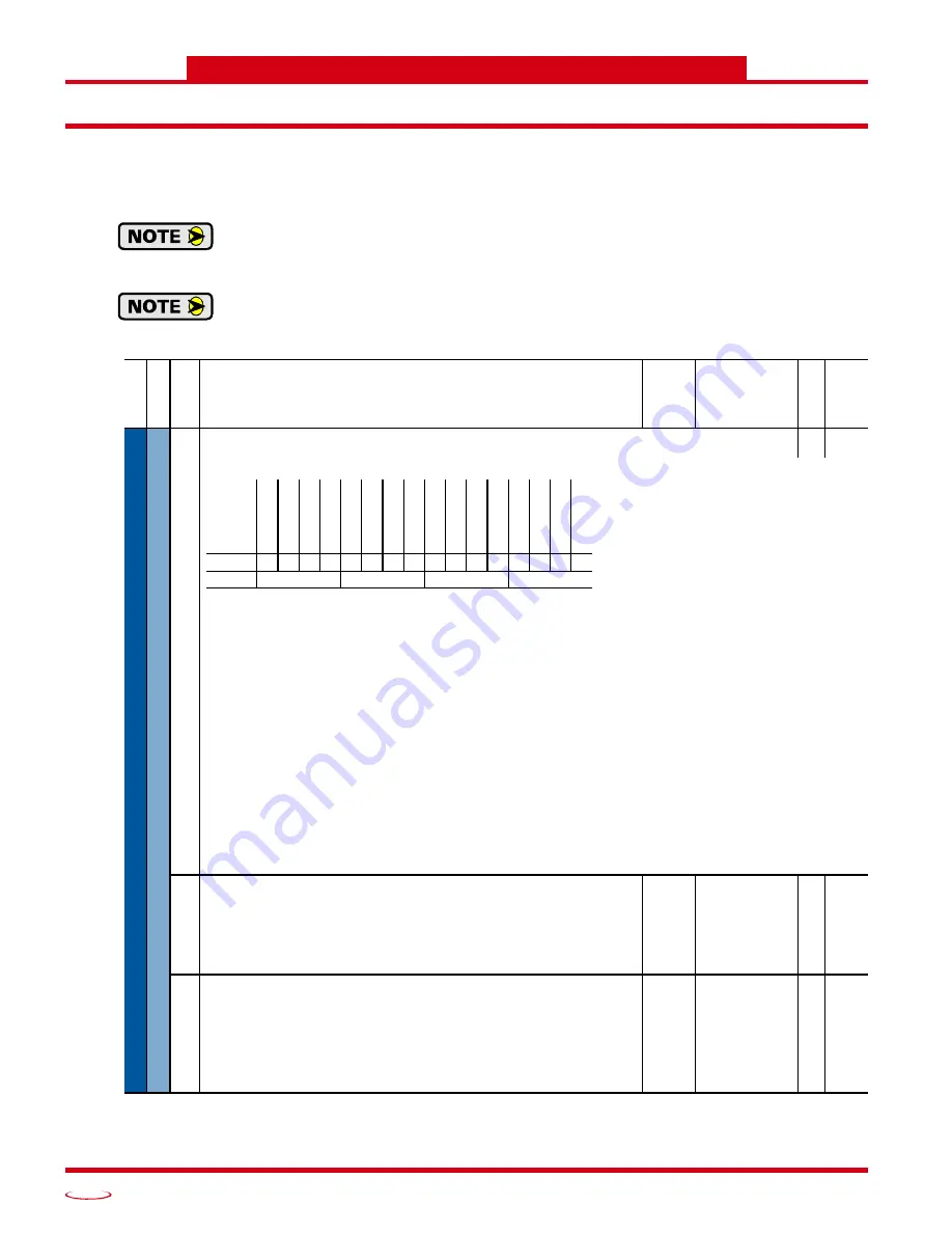
1
Encoder Cfg
Encoder Configure
RW 16-bit
integer
Configures the count direction and active encoder channels
Bit 0: “Z Chan Enable” – If this bit is reset to “0”, the RD750 will not generate Marker Events, which indicate that the resolver position
has passed through electrical zero. If set to “1”, Marker Events are generated. Marker Events are indicated by bit 8 of the
Encoder Status word (P5.8) Note that the RD750 always generates Z-pluses on the encoder outputs as well as in the Encoder
Status bits reported to the drive.
Bit 1: “A Chan Only” – Not used by the RD750, but the state of this bit affects the operation of the PowerFlex drive. It is strongly sug-
gested that this bit always be reset to “0”. If this bit is set to “1”, the drive will ignore errors reported in the “Quad Loss Count”
register (P8) and the number of counts per turn generated by the RD750 must be set to less than or equal to 20,000 instead of
80,000.
Bit 2: “Edge Mode” – When this bit is reset to “0”, the PowerFlex drive uses an accumulated count to determine the speed of the motor.
When this bit is set to “1”, the PowerFlex drive calculates speed based on the time between changes in resolver position.
Bit 3: “Inv Home In” – Not used by the RD750.
Bit 4: “Single Ended” – Not used by the RD750, but the state of this bit affects the operation of the PowerFlex drive. It is strongly sug-
gested that this bit always be reset to “0”. If this bit is set to “1” the PowerFlex drive will ignore errors reported in the “Phase
Loss Count” register (P7).
Bit 5: “Direction” – Used to reverse the direction of rotation needed to produce an increase in position counts. It is also possible to
reverse count direction by reversing the S2-S4 connection at the resolver input connector. When the resolver is connected as
shown in Figure 9,
, resetting this bit to “0” results in clockwise increasing counts when looking at the
resolver shaft. Setting this bit to “1” results in counter-clockwise increasing counts.
Using either of the two methods to reverse count direction will result in a change in position value reported to the
PowerFlex drive by the RD750. In some cases, this change in position value may cause erratic movement or
behavior when the drive is commanded to power a motor. Because of this, it is strongly recommended that you
issue a software reset or cycle power to the drive after the count direction is reversed.
2
Encoder PPR
Encoder Pulses Per Revolution
Configures the drive for the number of Pulses Per Revolution (encoder lines) emulated by
the RD750. This parameter must be set to ({Resolver Position Resolution x Resolver
Speed} / 4). Resolver Position Resolution is set by the DIP switches on the RD750.
Resolver Speed is an inherent property of the resolver. For example, when using 14 bit
position resolution and a 2X speed resolver, the Encoder PPR must be set to:
({16,384 x 2} / 4) = 8,192.
Default:
Min/Max:
1024
2 / 20000
RW Real
3
Fdbk Loss Cfg
Feedback Loss Configure
Configures how the drive reacts to an error status condition for the feedback.
“Ignore” (0) – No action taken
“Alarm” (1) – Type 1 alarm indicated
“Flt Minor” (2) – Minor fault indicated. If running, drive continues to run. Enable with
P950 [Minor Flt Cfg]. If not enabled, acts like a major fault.
“FltCoastStop” (3) – Major fault indicated. Coast to Stop.
Default:
Min/Max:
3 = “FltCoastStop”
0 = “Ignore”
1 = “Alarm”
2 = “Flt Minor”
3 = “FltCoastStop”
RW Real
Options
Re
se
rv
ed
Re
se
rv
ed
Re
se
rv
ed
Re
se
rv
ed
Re
se
rv
ed
Re
se
rv
ed
Re
se
rv
ed
Re
se
rv
ed
Re
se
rv
ed
Re
se
rv
ed
Di
re
cti
on
Si
ng
le
En
de
d
In
v Home In
Ed
ge
M
od
e
A
Ch
an
O
nl
y
Z Ch
an
Enb
l
Default
0
0
0
0
0
0
0
0
0
0
0
0
0
0
0
0
Bit
15 14 13 12 11 10 9
8
7
6
5
4
3
2
1
0


