


7
Inspect installation and ensure that it has
been carried out in accordance with these
instructions. Ensure that electrical and gas
supplies are isolated. The gas supply should
be purged and tested for soundness in
accordance with the BS6891:1988, BGIM/16,
IGE Report 1M/2 and any other British
Standard and Codes of Practice. Open
isolating valve.
Remove the combustion chamber cover
plate by unscrewing 6 fixing screws. Take
care not to damage the sealing gasket.
Open the control housing cover by
unscrewing the securing screws. Ensure all
internal components are securely fixed and
all connections securely made.
Switch on the electrical supply to the heater
and observe the correct start up sequence as
follows:
The mains lamp (red) will illuminate. The ID
fan will start to run and the vacuum switch
checking relay (inside flame electronic
sequence control box) will pull in. Safe start
checks are carried out automatically and a
purge period of approximately 9 seconds will
commence.
At the end of the purge period the ignition
sequence will commence. The spark ignition
will be energised producing a spark at the
ignition electrode. The gas shut off valve
will at the same time be energised. If
ignition is successful the flame is detected
by the flame sensing probe and the ignition
spark will be switched off. The ‘burner on’
(amber) lamp indicates that the gas safety
control valves are energised.
If the ignition is unsuccessful the gas safety
control valve is closed and the spark ignition
de-energised after approximately 5 - 7
seconds.
After an unsuccessful ignition attempt the
electronic sequence controller will ‘lock out’.
The ‘power lamp’ (red) only will remain
illuminated and the fan will continue to run.
To reset this ‘lock out’ condition, switch the
power supply to the heater, wait 5 seconds
then restore it. If repeated lock out occurs
investigate cause.
In the event of an electrical fault after
installation of the appliance preliminary
electrical systems checks should be carried
out (re earth continuity polarity and
resistance to earth).
To shut down the heater, switch off the
power supply to the heater. Automatic
control of the heater or a series of heaters
may be achieved by incorporating
thermostats, time switches, frost
thermostats, manual over-ride switches etc,
in the electrical supply to the heater(s). It is
essential to allow a delay of 15 seconds
after switching off a heater before
attempting to restart.
If at any time after completion of the start
up sequences, loss of flame should occur,
the electronic sequence controller will
attempt to re-ignite. If this is unsuccessful
lock out will occur.
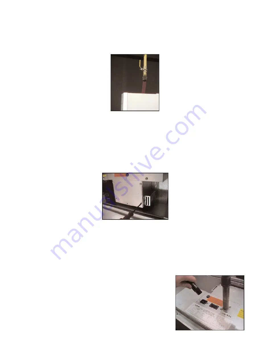
Set burner gas pressure as follows:
Isolate gas supply. Unplug mains input
connector to heater.
12 Commissioning for
individually flued and unflued
heaters
When the Vision Compact heater is to be
installed in locations where there is airborne
dust or where there is a polluted atmos-
phere e.g. chlorinated vapours, process dust
etc., a ducted fresh air supply must be pro-
vided to the burner. Where a fresh air duct-
ed inlet is to be fitted to the burner assem-
bly the aluminised steel air intake grill must
be removed from the burner casing and the
D/A fitting attached over the burner orifice
plate.
These models incorporate a 100mm (4in)
fresh air duct connection (Pt. No.
M201601-SUB). A fresh air duct of
minimum 100mm (4in) diameter should be
connected to the D/A duct. A flexible joining
piece should be used, available from the
manufacturer (Pt. No. 7531), fixed with hose
clips to facilitate disconnection when
servicing the burner.
The maximum length of fresh air inlet duct
is 7 m of 100mm (4in) diameter duct, the
maximum number of bends is two. The fresh
air inlet duct can be installed either
vertically or horizontally. A position should
be selected for the inlet of the fresh air duct
so that it will receive dust free clean air. A
cowl of the British Gas tested and certified
type, such as the GCI or GLC terminal,
should be fitted at the inlet of the duct. If
the duct inlet is located on a roof the
underside of the inlet cowl must be at least
600mm (2ft) above roof level and at least
250mm (10in) higher than any projection on
the roof within a 2m radius of the cowl.
11 Fresh air ducted inlet (all
models)
Figure 5
Figure 6
Figure 7


