background image


Settings 


32


 A  BAH0040-9  01.19


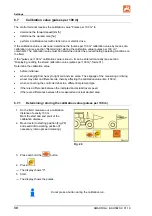
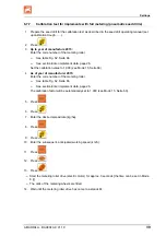
6.7.3 

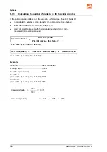
Calculating the number of crank turns for the calibration test 

If the calibration value differs from the values in the Table (see Chap. 9.3, Seite 62) 


recalculate the number of crank turns for the calibration test (see below) 


enter the number of crank turns in Table (Fig. 61) 


carry out a calibration test with the calculated number of crank turns  
(see seed drill operating manual). 


Conversion factor  = 

Pul./100 m (actual) 


Pul./100 m (value from Table) 

1)


1) 

see Tables (see Chap. 9.3, Seite 62) 


Crank turns (actual)  = 

Crank turns (value from Table) 

1)

  x 

Conversion factor 

1) 

see Tables (see Chap. 9.3, Seite 62) 


Example: 

Seed drill: ............................................... AD-P 03 Special 

Working width: ....................................... 3.00 m 

Pul./100 m (measured): ......................... 1339 

Pul./100 m  
(from Tables (see Chap. 9.3, Seite 62):  1409 

Crank turns  
(from Tables (see Chap. 9.3, Seite 62):  38.5 


Conversion factor  = 

1339 

=  0.95 

1409 


Crank turns (actual) 

=  38.5  x  0.95  =  36.6 


Содержание AmaDrill+

Страница 1: ...Operating manual az Control terminal AmaDrill MG3856 BAH0040 9 01 19 Please read and observe this operating manual before initial operation of the implement Keep it in a safe place for future use en ...

Страница 2: ... person concerned would not only harm himself but also make the mistake of blaming the machine for the reason of a possible failure instead of himself In order to ensure a good success one should go into the mind of a thing or make himself familiar with every part of the machine and to get acquainted with its handling Only this way you would be satisfied both with the machine as also with yourself...

Страница 3: ... amazone de Spare part orders Spare parts lists are freely accessible in the spare parts portal at www amazone de Please send orders to your AMAZONE dealer Formalities of the operating manual Document number MG3856 Compilation date 01 19 Copyright AMAZONEN WERKE H DREYER GmbH Co KG 2019 All rights reserved Reprinting even of sections only possible with the approval of AMAZONEN WERKE H DREYER GmbH ...

Страница 4: ... have chosen one of the quality products from the wide product range of AMAZONEN WERKE H DREYER GmbH Co KG We thank you for your trust in our products Before initial operation read and observe this operating manual and particularly the safety information ...

Страница 5: ...g the working width 27 6 3 Displaying altering the target blower fan speed during standstill 27 6 4 Displaying altering the target blower fan speed during operation 28 6 5 Displaying altering the tramline rhythm 28 6 6 Calibration of the Vario gearbox 29 6 7 Calibration value pulses per 100 m 30 6 7 1 Determining storing the calibration value pulses per 100 m 30 6 7 2 Displaying editing the stored...

Страница 6: ... display A3 48 8 2 Fault display A4 48 8 3 Fault display A5 49 8 4 Fault display A6 DMC Primera only 50 8 5 Fault display A7 51 8 6 Fault display A8 51 8 7 Fault display A9 51 8 8 Fault display A10 52 8 9 Fault display A11 52 8 10 Fault display A12 52 8 11 Fault display A13 53 9 Tables 54 9 1 Machine data table 54 9 2 Table for adjustable tramline rhythms 61 9 3 Table for calibration values crank ...

Страница 7: ...nual All the directions specified in the operating manual are always seen in the direction of travel 1 1 Diagrams Instructions and responses Activities to be carried out by the user are given as numbered instructions Always keep to the order of the instructions The reaction to the handling instructions is given by an arrow Example 1 Instruction 1 Implement response to instruction 1 2 Instruction 2...

Страница 8: ...ion of the contract Guarantee and liability claims for damage to people or property will be excluded if they can be traced back to one or more of the following causes Non intended use of the control terminal Improper installation commissioning and operation of the control terminal Non compliance with the instructions in the operating manual regarding commissioning operation and maintenance Unautho...

Страница 9: ...oduct Do not subject the control terminal to any mechanical vibrations or impact Do not allow the control terminal to fall Do not touch the display of the control terminal with sharp objects as this could damage the display Protect the control terminal from wetness and moisture Do not place the control terminal near heat sources such as radiators or ovens Never open the housing of the control term...

Страница 10: ...te death or serious physical injury WARNING Indicates a medium risk which could result in death or serious physical injury if not avoided If the instructions are not followed then this may result in death or serious physical injury CAUTION Indicates a low risk which could cause minor or medium level physical injury or damage to property if not avoided IMPORTANT Indicates an obligation to special b...

Страница 11: ...9 11 3 Product description Fig 1 Standard equipment Fig 1 Special equipment Fig 1 1 Control terminal with fastening bracket 2 Socket connection 12V 3 Wiring harness with 20 pin connector 4 Bracket with battery cable choice of one or two sockets ...

Страница 12: ...s observing all instructions in this operating manual Other uses to those specified above are forbidden and shall be considered as improper For any damage resulting from improper use the operator bears the sole responsibility AMAZONEN WERKE accepts no liability 3 2 CE marking The CE marking Fig 2 signalises compliance with the stipulations of the valid EU directives Fig 2 Electrical equipment Batt...

Страница 13: ...ed with an EEPROM memory chip for storing data The data are again available for the next use even after a long period of deactivation of the on board power supply Fig 3 4 1 Operation with DMC Primera direct seed drills The control terminal issues an alarm when the set minimum fertiliser quantity is reached in the fertiliser hopper 4 2 Rotary cultivator operation The control terminal monitors the f...

Страница 14: ...nd the tramline marker indicates the position of the hydraulically operated track markers initiates an alarm when the set minimum quantity is reached in the tank fill level sensor required 4 3 1 Operation with cam wheel seed drill The AmaDrill monitors the lay shaft drive Fig 4 1 for seed drills equipped with tramline control Fig 4 The AmaDrill regulates and controls the seeding rate via the seed ...

Страница 15: ...gulates the electric gear motor for a uniform seeding rate Pneumatic seed drills are equipped with different electric gear motors When entering the implement data the AmaDrill requires the precise type designation of your electric gear motor in coded form The type designation is on the rating plate of the electric gear motor e g Electric gearbox EA365 Fig 6 1 Fig 6 Electric gear motor EA423 Fig 7 ...

Страница 16: ... The AmaDrill monitors the tramline control in the distributor head Fig 10 1 An acoustic alarm sounds in the event of incorrect shutter position Fig 10 Blower fan The control terminal monitors the fan speed If the actual speed deviates by more than 10 from the target speed an acoustic signal is initiated and in the display the control lamp Fig 11 1 above the speed symbol Fig 11 2 flashes The speed...

Страница 17: ...r 1 Forward speed km h pulses from the distance sensor 2 Tramline counter position Control terminal data 3 or 4 Control symbol Left track marker in working position pulse e g from track marker sensor Control symbol Right track marker in working position Display appears automatically in event of faults 5 Control symbol Refill hopper pulses from level sensor 6 Control symbol Blower fan speed deviati...

Страница 18: ...g Display target spread rate kg ha Reduce the displayed value the spread rate Increase the displayed value the spread rate Input display of working width m Input display of a soil dependent number of pulses of a 100 m long calibration distance Yellow button Input display of fan nominal speed rpm Input of tramline rhythm Select and change mode and code Settings for calibration test Fig 14 ...

Страница 19: ...g gear seeder Calibrate the Vario gearbox with seed rate remote control Blue button Display of fan speed Alternative via button actuation Display of the cultivated part area ha total area ha Alternative via button actuation 1 Display current Working speed km h Tramline counter 2 Display current Spread rate kg Tramline counter Full metering display Metering roller speed Valve timing gear display Sc...

Страница 20: ...ced seed rate is adjustable see section Machine data table Mode 7 Seite 56 The seeding rate must not be reduced when creating the tramlines with Seed drills D9 Seed drills AD Seed drills AD P 3000 3500 4000 Super Special Seed drills D9 and AD For D9 and AD seed drills the drive shafts of the tramline metering wheels remain at a standstill when creating the tramlines AD P 3000 3500 4000 Super Speci...

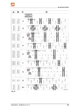
Страница 21: ... tramline rhythm Seite 28 The control terminal counts up the tramlines in the tramline counter after actuation of the track markers e g before turning at the end of the field after the machine is raised without track markers e g for turning at the end of the field The tramline counter can be blocked see section Block the tramline counter Seite 43 before raising the track marker e g before an obsta...

Страница 22: ...g 16 using various examples A Working width of the seed drill B Tramline spacing working width fertiliser spreader field sprayer C Tramline rhythm entered on the control terminal D Tramline counter during operation the field passes are numbered consecutively and displayed on the control terminal ...

Страница 23: ...Layout and function AMADRILL BAH0040 9 01 19 23 Fig 16 ...

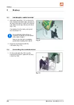
Страница 24: ... to access Fig 17 2 The distance from the radio unit or aerial must be at least 1 m Fig 17 The control terminal must have a conductive connection via the bracket to the tractor chassis Remove the paint at the installation points before installing the bracket 2 Equip the control terminal with the counterpart Fig 17 3 5 2 Connecting the control terminal 1 Fit the counterpart Fig 18 1 onto the bracke...

Страница 25: ...ainst unintentional release by means of a spring loaded lever Actuate the lever before releasing the implement plug 5 3 Switching the control terminal on off Switch the control terminal on and off by pressing the button Enter the implement specific data see section Settings Seite 26 When the control terminal is switched back on the data is available again Before using a seed drill of a different t...

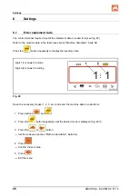
Страница 26: ...e Seite 54 Press the button repeatedly to display the inventory data Digit 1 1 shows the mode Digit 2 2 shows the coding Fig 20 Open the necessary modes 1 2 3 etc and enter the machine data in coded form 1 Press buttons and 2 Press the button repeatedly until the desired mode is displayed Fig 20 1 3 Press the or button Set the code see section Machine data table Seite 54 4 Press Confirm the set va...

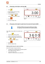
Страница 27: ... see below on single grain seed drills ED with micropellet spreader This setting is only possible for pneumatic seed drills 1 Press the button yellow Display Target blower fan speed rpm 2 Change the target blower fan speed with the and buttons 3 Press Store the selected value Fig 22 Switching off the blower fan speed monitoring Switch off the blower fan speed monitoring on single grain seed drills...

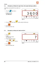
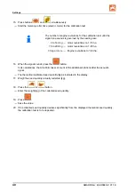
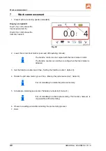
Страница 28: ...d drills 1 Press the button blue Display Fig 23 Current fan speed e g 3600 rpm Fig 23 2 Press the button and button yellow simultaneously 3 Press Save the selected value 6 5 Displaying altering the tramline rhythm 1 Press Display Stored tramline rhythm e g 7 Fig 24 2 Change the tramline rhythm with the and buttons 3 Press Save the selected value Fig 24 ...

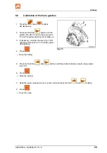
Страница 29: ... 0 and the yellow LED Fig 25 2 lights up 3 If necessary unscrew the lever Fig 25 3 until the pointer is set to 0 and the yellow LED lights up 4 Press Save the setting Fig 25 5 Press and hold the and buttons until the pointer indicates a scale value greater than 80 6 Press Store the setting 7 Read the scale value and enter it on the control terminal with the and buttons 8 Press Save the value ...

Страница 30: ...s per 100 m Seite 31 Determine the calibration value before initial use when changing from heavy to light soil and vice versa The slippage of the measuring or driving wheel may alter on different soils thereby affecting the calibration value imp 100 m when connecting the control terminal to a different implement type if there is a difference between the indicated and actual travel speed if there a...

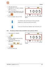
Страница 31: ...7 The calibration value imp 100 m must not be less than 250 Otherwise the control terminal will not work properly You can enter the determined calibration value in the table Fig 61 6 7 2 Displaying editing the stored calibration value pulses per 100 m 1 Bring implement to a standstill 2 Press Display The stored calibration value pul 100 m e g 1053 Fig 28 3 Alter the stored calibration value imp 10...

Страница 32: ...on test with the calculated number of crank turns see seed drill operating manual Conversion factor Pul 100 m actual Pul 100 m value from Table 1 1 see Tables see Chap 9 3 Seite 62 Crank turns actual Crank turns value from Table 1 x Conversion factor 1 see Tables see Chap 9 3 Seite 62 Example Seed drill AD P 03 Special Working width 3 00 m Pul 100 m measured 1339 Pul 100 m from Tables see Chap 9 3...

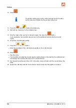
Страница 33: ...Using the or buttons enter the code number see table of the metering wheel Mechanical seed drills Pneumatic seed drills Metering wheel Normal seed metering wheel Fine seed metering wheel Metering roller Code number 3 1 See table Fig 62 Seite 66 4 Press 5 Press 6 Enter the desired spread rate kg ha 7 Press 8 Read the scale value e g 50 for the first calibration test from the seed drill operating ma...

Страница 34: ...es account of the additional rotations after the acoustic signal 16 Weigh the collected seed quantity 17 Press the or button Enter the weight kg of the collected seed quantity on the control terminal 18 Press Save the value The AmaDrill calculates the required gearbox setting based on the data from the calibration test and displays the required scale value on the control terminal 19 Set the gearbo...

Страница 35: ...tion trough etc 2 Press 3 Press the or button Enter the desired application rate kg ha 4 Press 5 Press 6 Press the or button Enter the scale value of the pointer e g 50 refer to the seed drill operating manual for the first calibration test Fig 30 2 7 Press 8 Press the and buttons simultaneously The pointer Fig 30 2 moves to the scale value entered e g 50 The scale value must be the same as the ge...

Страница 36: ...e additional rotations after the acoustic signal 11 Weigh the collected seed quantity 12 Press the or button Enter the weight kg of the collected seed quantity 13 Press Save the value The AmaDrill calculates the required gearbox setting based on the data from the calibration test The pointer Fig 30 2 moves to the calculated scale value 14 Repeat the calibration test with the last gear setting to v...

Страница 37: ... 1 Prepare the seed drill for the calibration test as described in the seed drill operating manual set up calibration trough etc 2 Press 3 Press the button or button Enter the code number Mechanical seed drills Pneumatic seed drills Metering wheel Normal seed metering wheel Fine seed metering wheel Metering roller Code number 3 1 See table Fig 62 Seite 66 4 Press 5 Press 6 Enter the desired spread...

Страница 38: ...ee section Calibration of the Vario gearbox Seite 29 12 Start with the crank turns for the calibration test 13 Stop the cranks when you hear an acoustic signal then press the button In its calculations the AmaDrill takes account of the additional rotations after the acoustic signal 14 Weigh the collected seed quantity 15 Press the or button Enter the weight kg of the collected seed quantity 16 Pre...

Страница 39: ...lue to 1 000 see Mode 15 Seite 60 4 As of year of manufacturer 2015 Enter the code number of the metering roller See table Fig 62 Seite 66 See section Enter implement data page 26 The calibration factor will be automatically set to 1 000 see Mode 15 Seite 60 5 Press 6 Press 7 Enter the desired spread rate kg ha 8 Press 9 Press 10 Enter the subsequent anticipated working speed km h 11 Press 12 Pres...

Страница 40: ...a 30 kg or more Engine revolutions to 1 40 ha 16 When the signal sounds press the button In its calculations the AmaDrill takes account of the additional rotations after the acoustic signal The theoretical calibrated seed quantity kg is indicated in the display 17 Weigh the seed quantity actually collected kg 18 Press the or button Enter the weight kg of the collected seed quantity 19 Press Save t...

Страница 41: ...ir stream After approx 3 seconds the time can be set in Mode 8 when the seed has arrived in the coulters the driver starts up the tractor 6 8 1 Start up ramp When starting the tractor the control terminal receives the first pulse The metering roller then rotates for approx 10 seconds adjustable in Mode 9 at 50 adjustable in Seite 56 of the simulated tractor speed and then with the actual values Th...

Страница 42: ... track marker control The tramline counter can continue counting when the track marker is actuated 3 Set the tramline counter see Chap Setting the tramline counter Seite 43 4 Delete the part area memory see Chap Erasing the part area memory Seite 44 It is not mandatory to delete the part area memory 5 Activate pre metering see section Activate pre metering Seite 41 It is not mandatory to activate ...

Страница 43: ...line counter is displayed e g Tramline counter 2 see Fig 16 Seite 23 under the lettering START 7 1 2 Block the tramline counter Press Further advancing of the tramline counter is blocked The number Fig 33 1 of the tramline counter flashes on the display The control symbol Fig 33 2 marks the stop symbol Press The tramline counter is active again Fig 33 ...

Страница 44: ...ig 34 7 2 2 Erasing the part area memory 1 Press and hold the button 2 Press The part area memory is set to 0 ha 3 Press the button Back to the work display Fig 36 or Fig 37 7 2 3 Display the total area 1 Press the button twice Display Fig 35 total worked area e g 105 1 ha Fig 35 The data cannot be deleted 2 Press Back to work display Fig 36 or Fig 37 ...

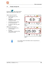
Страница 45: ... km h the setting of the tramline counter Fig 36 2 e g tramline counter 3 the left track marker Fig 36 3 is in the working position the right track marker Fig 36 4 is raised Fig 36 Display during work Fig 37 current spread rate Fig 37 1 e g 125 0 kg ha the setting of the tramline counter Fig 37 2 e g tramline counter 3 Fig 37 The counting process of the tramline counter is supported by an acoustic...

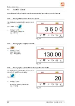
Страница 46: ...ible for pneumatic seed drills Press button blue Display Fig 38 current blower fan speed e g 3600 rpm Fig 38 7 4 2 Displaying the target spread rate Press Display Fig 39 target spread rate e g 130 0 kg ha Fig 39 7 4 3 Displaying the speed of the metering roller drive motor This display is only possible for pneumatic seed drills with full metering functionality Press Display Fig 40 Momentary meteri...

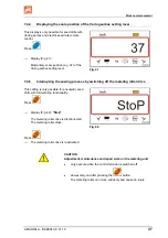
Страница 47: ...upting the sowing process by switching off the metering roller drive This setting is only possible for pneumatic seed drills with full metering functionality Press Display Fig 42 Stop The metering roller drive is disconnected The metering roller stops Press The metering roller drive is reactivated Fig 42 CAUTION Adjustment maintenance and repair work on the metering unit only execute when the cont...

Страница 48: ... display A4 Alarm message at standstill of the universal joint shaft of the active soil tillage implement e g of the rotary cultivator The control terminal issues an alarm as soon as the overload clutch of the universal joint shaft of the soil tillage implement is activated When the universal joint shaft is at standstill the following appears the display Fig 44 an acoustic signal Fig 44 ...

Страница 49: ...he DMC Primera only on machines with combined seed level and seeding shaft monitoring In the event of an alarm the display Fig 45 appears an acoustic signal triple signal tone is emitted Fig 45 The display switches in the event of insufficient seed quantity The control symbol Fig 46 1 marks the fill level symbol The alarm is repeated when the machine is used again e g after turning at the end of t...

Страница 50: ...ic signal triple signal tone is emitted Fig 47 The display switches in the event of insufficient fertiliser The control symbol Fig 48 1 marks the fill level symbol The alarm is repeated when the machine is used again e g after turning at the end of the field Fig 48 Switching off the alarm message 1 Press and hold button blue 2 Press The warning message is switched off The alarm message can only be...

Страница 51: ...ring Metering roller control defective Fig 50 8 7 Fault display A9 Seed drills with Vario gearbox The actual position of the gear setting lever does not correspond to the target position The gearbox setting lever does not point to the required scale value Pneum seed drills with full metering The required speed of the metering roller is not reached Reduce the working speed Fig 51 ...

Страница 52: ...ing The maintenance flap of the metering unit is open Fig 52 8 9 Fault display A11 Interruption during zero point travel see section Calibration of the Vario gearbox Seite 29 Fig 53 8 10 Fault display A12 Pneum seed drills with full metering The target spread rate cannot be maintained Fig 54 ...

Страница 53: ...rpm the electric motor that drives the metering roller in the metering unit stops Fig 55 Switching off the alarm message 1 Increase the blower fan speed to the required rpm 2 Press as soon as the blower fan speed is above 200 rpm The warning message is switched off The metering roller in the metering unit is turning with the required speed ...

Страница 54: ... 1 Fig 57 Machine with 1 track marker sensor on marker changeovers Fig 58 1 Fig 58 2 to 99 The tramline counter counts the field passes When lifting the track marker e g when lifting the seed drill to turn at the end of the field the tramline count will be increased If the seed drill does not have a track marker sensor enter a number between 2 and 99 The number equals the time in seconds between l...

Страница 55: ... and triggering of the alarm 00 Alarm is switched off 10 Setting for pneumatic seed drills 10 seconds 22 Setting for cam wheel seed drills 22 seconds Mode 5 Code The period in which no alarm must be triggered for cam wheel seed drills between the command to create tramlines and standstill of the lay shaft for pneumatic seed drills between the command to create tramlines and closing of the outlets ...

Страница 56: ...0 0 to 100 freely adjustable values Mode 8 Code Pre metering time when pressing the button filling of the metering roller chambers in the metering unit see section Pre metering prior to startup page 41 3 Factory set value 3 seconds 0 to 5 Adjustable values from 0 to 5 seconds Mode 9 Code Pre metering time when starting up start up ramp see section Start up ramp page 41 10 Factory set value 10 seco...

Страница 57: ...ing speed 0 km h no simulation 0 to 30 Simulated working speed from 0 to 30 km h Mode 12 Code Seed quantity alteration via button actuation 10 Factory set value 10 0 to 100 Adjustable values from 0 to 100 Mode 13 Code Type and setting of the working position sensor 00 Digital sensor 0 5 to 4 5 Analogue sensor When lifting the machine the metering motor switches off when reaching the height entered...

Страница 58: ...ing roller drive gearbox actuator 0 Without electric metering roller drive gearbox actuator 1 Electric gear motor 1 EA423 see rating plate 2 Electric gear motor 1 EA365 see rating plate 3 Electric cylinder 12 V stroke 130 mm 1 for seed rate remote control ...

Страница 59: ... AMADRILL BAH0040 9 01 19 59 Mode 14 Code Metering drive type 4 Electric gear motor 1 EA419 see rating plate 5 Electric gear motor 1 EA399 see rating plate This motor is installed e g on micropellet spreaders ...

Страница 60: ...e sensor When lowering the machine the metering motor switches on when the set height is reached Enter the height as voltage value 0 5 to 4 5 V The value in Mode 16 cannot be smaller than the value in Mode 13 Smaller value switch on the metering motor at low height Higher value switch on the metering motor at greater height Mode 17 Code Segment distributor head 0 Implement does not have a segment ...

Страница 61: ... 4 4 4 4 5 5 4 4 4 5 5 5 5 6 6 5 5 5 6 6 6 0 7 6 6 6 7 7 8 8 7 7 7 8 9 0 8 8 8 10 10 9 9 9 10 10 10 11 11 11 12 12 13 Fig 59 Tramline rhythms 15 16 17 20 21 22 23 26 32 35 Tramline counter controlled and displayed by the control terminal 1 0 0 0 0 0 0 0 0 0 1 1 1 0 0 0 1 0 1 2 2 2 1 1 1 2 1 2 3 3 3 2 2 2 3 2 3 4 4 4 3 3 3 4 3 4 5 5 5 4 4 4 5 4 5 6 6 6 5 5 6 5 6 7 7 7 6 6 7 6 7 8 8 8 7 8 7 8 9 9 9 ...

Страница 62: ... test can be recalculated see front The rotational speed of the electric drive motor during the calibration test is automatically based on the actual calibration value pul 100 m Mechanical seeding technology Mounted seed drills D9 Super Special Working width 2 5 m 3 0 m 3 5 m 4 0 m 6 0 m Tyres Calibration value imp 100 m Crank turns on 1 40 ha 6 00 16 180 90 16 740 46 0 38 5 33 0 10 0 75 15 711 28...

Страница 63: ...5 33 0 29 0 AD P 03 Super with star wheel drive 1575 29 5 22 0 AD P 03 Special AD P 03 Super With pulse wheel 1230 Pack top seed drills pneumatic Calibration value imp 100 m AD P 30 35 4000 Special With radar 9700 AD P 30 35 4001 Special With radar 9700 Pack top seed drills pneumatic Calibration value imp 100 m AD P 30 4000 SUPER With radar 9700 Tine seed drills pneumatic Calibration value imp 100...

Страница 64: ...00 Primera 602 Primera 9000 Primera 12000 Crank turns on 1 40 ha 68 0 45 3 34 0 22 7 16 8 Calibration value imp 100 m 1023 Predecessor machines Mounted seed drills mechanical Working width 2 5 m 3 0 m 4 0 m Calibration value imp 100 m Crank turns on 1 40 ha AD 03 617 27 0 22 5 17 0 RP AD 03 672 59 0 49 0 37 0 Pack top seed drills pneumatic Working width 2 5 m 3 0 m 4 0 m Calibration value imp 100 ...

Страница 65: ...Tables AMADRILL BAH0040 9 01 19 65 9 4 Table for calibration values crank turns for the calibration test Field Calibration value pul 100 m Crank rotations Fig 61 ...

Страница 66: ...Tables 66 AMADRILL BAH0040 9 01 19 9 5 Table for metering roller code number Code no Metering roller 1 7 5 cm3 20 cm3 40 cm3 2 120 cm3 210 cm3 350 cm3 3 600 cm3 660 cm3 880 cm3 Fig 62 ...

Страница 67: ...no Metering roller Note 3 700 cm3 Metering roller 700 cm3 suitable for metal metering housings see fig not suitable for plastic metering housings Fig 63 Code number input see section Calibration test for implements with full metering page 39 ...

Страница 68: ...te reduction 100 x number of tramline seeding coulters Number of seeding coulters 9 6 2 Table for seed rate reduction Working width Number of seeding coulters Number of tramlines_ Seeding coulters Recommended seed rate reduction when creating tramlines 3 0 m 18 4 22 18 6 33 18 8 44 24 4 17 24 6 25 24 8 33 3 43 m 21 4 19 21 6 29 21 8 38 3 50 m 21 4 19 21 6 29 21 8 38 28 4 14 28 6 21 28 8 28 4 0 m 2...

Страница 69: ...mmended seed rate reduction when creating tramlines 4 5 27 4 15 27 6 22 27 8 30 36 4 11 36 6 17 36 8 22 5 0 m 40 4 10 40 6 15 40 8 20 6 0 m 36 4 11 36 6 16 36 8 22 48 4 8 48 6 12 48 8 17 8 0 m 64 4 6 64 6 9 64 8 12 9 0 m 72 4 6 72 6 8 72 8 11 12 0 m 72 4 6 72 6 8 72 8 11 96 4 4 96 6 6 96 8 8 15 0 m 90 4 4 90 6 7 90 8 9 ...

Страница 70: ......

Страница 71: ......

Страница 72: ...H DREYER GmbH Co KG Postfach 51 D 49202 Hasbergen Gaste Germany Tel 49 0 5405 501 0 email amazone amazone de http www amazone de ...

Отзывы: