background image

25

EN

NOTICE


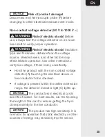
Risk of product damage!


Disconnect the thermocouple probe (R) before 
changing to other electrical measurement mode.

Non-contact voltage detector (90 V to 1000 V ~)


WARNING


Risk of electric shock!

 Before 

use, always test the voltage detector on a known 
live circuit to verify proper operation.


WARNING


Risk of electric shock!

 Insulation 

type and thickness, distance from the voltage 
source, shielded wires, and other factors may 
effect reliable operation. Use other methods to 
verify live voltage, if there is any uncertainty. 

•  Hold the product with the non-contact voltage 

detector (A) touching the electrical device or 
live conductor to be checked. 

•  If voltage is present within the defined detection 

range, the detector indicator light (C) lights up. 

NOTICE

 The conductors in electrical cords 

are often twisted. For best results, rub the tip along 
the length of the cord to ensure getting the tip in 
close proximity to the live conductor.

NOTICE

 The product has high sensitivity. It is 

normal in its operation that static electricity or other 
sources of energy may randomly trip the sensor.

Содержание B07VX43ZKN

Страница 1: ...NCV Flashlight 4000 Count Pinza Amperim trica CA de 1000 A True RMS NCV Linterna 4000 Cuentas Pince Amp rem trique AC 1000 A Valeur Efficace Vraie D tection de Tensions sans Contact NCV Lampe Torche...

Страница 2: ...English 3 Espa ol 33 Fran ais 66...

Страница 3: ...owing WARNING Risk of electric shock Improper use of this product can cause damage shock injury or death WARNING Risk of electric shock The safety features of this product may not protect the user if...

Страница 4: ...only Do not exceed the maximum allowable input range of any measurement mode Mode Maximum Input A 1000 A V 1000 V Resistance Capacitance Frequency Diode Test Temperature 1000 V Do not measure current...

Страница 5: ...device under test before performing diode resistance or continuity tests Voltage checks on electrical outlets can be difficult and misleading because of the uncertainty of connection to the recessed e...

Страница 6: ...Always remove the connector leads before replacing the battery Battery Warnings Always insert batteries correctly with regards to polarity and marked on the battery and the product Do not mix old and...

Страница 7: ...h a medium level of risk which if not avoided could result in death or serious injury NOTICE Indicates a practical tip advice or practice not related to personal injury CAUTION The signal word that in...

Страница 8: ...measurement up to 1000 A CAT II 1000V Product is designed to protect the user during measurements performed on circuits directly connected to the low voltage installation up to 1000 V CAT III 1000V Pr...

Страница 9: ...s and tools This product is for indoor use only This product may be used only under the conditions and for the purposes for which it was designed No liability will be accepted for damages resulting fr...

Страница 10: ...10 EN Product Description A B C D E F G H I M L K J N O P Q R S...

Страница 11: ...t voltage indicator M HOLD button D Clamp trigger N Flashlight E REL button O Battery compartment F Display P Test probes with connector leads G RANGE button Q Probe tip shrouds H MODE button R Thermo...

Страница 12: ...ing current voltage 8 Continuity 2 Minus sign 9 MAX MIN voltage peaks 3 DC Direct current voltage 10 REL Relative 4 H Display hold 11 Low battery 5 Auto power off 12 Unit of measurement 6 AUTO Automat...

Страница 13: ...3 EN Function switch Position Function Measurement AC current up to 1000 A AC current up to 400 A Temperature Diode test capacitance Resistance continuity DC voltage AC voltage Frequency duty ratio OF...

Страница 14: ...he low battery indicator 11 is shown on the display Turn the lock of the battery compartment cover O by 180 in an anti clockwise direction Open the battery compartment Replace 3 x 1 5 V AAA R03 batter...

Страница 15: ...shown on the display To deactivate automatic power off press and hold the MODE button H while switching the product on The indicator 5 goes off Switching the flashlight on off When switched on press a...

Страница 16: ...manual mode and to disable the automatic range setting The AUTO indicator 6 goes off By every press on the RANGE button G the relevant decimal place changes its position If a reading is higher than t...

Страница 17: ...s P from the product before making clamp measurements Set the function switch L to the 400A or 1000A position If the approx range of the measurement is not known select the highest range Then move to...

Страница 18: ...of short circuit Use the test probe shrouds Q to avoid accidental short circuiting if the components or test points are too near each other AC voltage measurement Insert the black connector lead P int...

Страница 19: ...voltage measurement Insert the black connector lead P into the negative COM black terminal I and the red connector lead P into the positive V red terminal J Set the function switch L to the position...

Страница 20: ...r the resistance is too high to measure The stabilized value on the display F is read as the actual reading Capacitance measurement NOTICE To avoid electric shock or measurement errors discharge the c...

Страница 21: ...pacitors follow the polarity of its leads to have a precise measurement Frequency duty cycle measurement Insert the black connector lead P into the negative COM black terminal I and the red connector...

Страница 22: ...probes P across the circuit or component being measured The stabilized value on the display F is read as the actual reading Continuity measurement Insert the black connector lead P into the negative C...

Страница 23: ...black terminal I and the red connector lead P into the positive V red terminal J Set the function switch L to the CAP position Press the MODE button H to change the measurement mode The indicator 7 i...

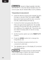
Страница 24: ...uple probe R to the thermocouple probe adapter S The polarity marking of the probe R must correspond to the marking of the adapter S The probe pins are made in varying sizes to avoid a wrong connectio...

Страница 25: ...able operation Use other methods to verify live voltage if there is any uncertainty Hold the product with the non contact voltage detector A touching the electrical device or live conductor to be chec...

Страница 26: ...do not immerse the product in water or other liquids Never hold the product under running water Cleaning To clean the product wipe with a soft slightly moist cloth If necessary clean the terminals I J...

Страница 27: ...range protection Maximum input 1000 A Frequency response 50 Hz to 60 Hz true RMS AC true RMS voltage Range Resolution Accuracy 4 V 1 mV 1 5 f m 5 digits 40 V 10 mV 400 V 100 mV 1000 V 1 V AC voltage b...

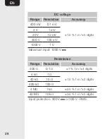
Страница 28: ...5 digits 4 V 1 mV 40 V 10 mV 400 V 100 mV 1000 V 1 V Maximum input 1000 V Resistance Range Resolution Accuracy 400 0 1 1 f m 4 digits 4 k 1 1 5 f m 2 digits 40 k 10 400 k 100 4 M 1 k 2 5 f m 3 digits...

Страница 29: ...its 4 F 0 001 F 40 F 0 01 F 400 F 0 1 F 4 mF 0 001 mF 5 f m 5 digits 40 mF 0 01 mF 5 f m 8 digits 100 mF 0 1 mF 5 f m 15 digits Frequency Range Accuracy 9 999 Hz to 99 99 kHz 1 2 f m 5 digits Frequenc...

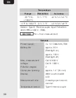
Страница 30: ...0 V RMS NOTICE fm from measurement General Power supply 3 x 1 5 V AAA R03 Battery life approx 30 h Flashlight on approx 100 h Flashlight off Max measurement voltage Cat IV 600 V Cat III 1000 V Polluti...

Страница 31: ...orage temperature 4 F to 140 F 20 C to 60 C Operating humidity max 80 up to 87 F 31 C decreasing linearly to 50 at 104 F 40 C Storage humidity 80 Operating altitude max 7000 2000 m Auto power off afte...

Страница 32: ...review AmazonCommercial is committed to delivering customer driven products that live up to your high standards We encourage you to write a review sharing your experiences with the product amazon com...

Страница 33: ...amazon com AmazonCommercial V01 10 19 MADE IN CHINA HECHO EN CHINA FABRIQU EN CHINE...

Отзывы: