Amarex KRT series Скачать руководство пользователя страница 40

5 Installation at Site

40 of 124

Amarex KRT

5.4.1.2 Level control

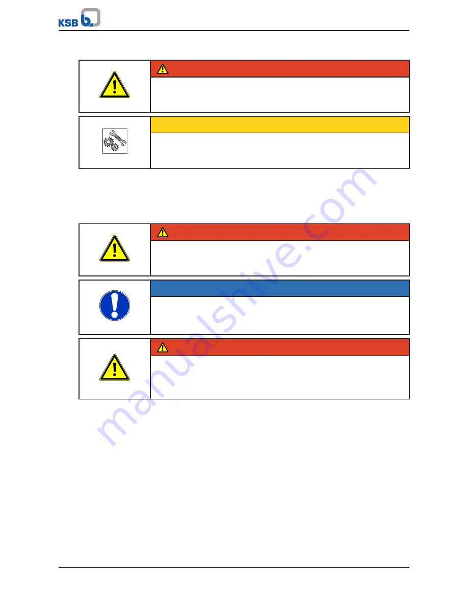
 DANGER

Pump set running dry

Explosion hazard!

Never allow a nonincendive pump set to run dry.

CAUTION

Fluid level below the specified minimum

Damage to the pump set by cavitation!

Never allow the fluid level to drop below the specified minimum.

Automatic pump set operation in a tank requires the use of level control equipment.
Observe the specified minimum fluid level. (

ð

 Section 6.2.4.2, Page 51)

5.4.1.3 Operation on a frequency inverter

The pump set is suitable for operation on a frequency inverter as per IEC 60034-17.

 DANGER

Operation outside the permitted frequency range

Explosion hazard!

Never operate an explosion-proof pump set outside the specified range.

NOTE

For pump sets with rated voltages exceeding 500 V, a dv/dt filter should be fitted at
the output of the frequency inverter to reduce the rate of voltage rise to the limits
specified in IEC 60034-17. Otherwise a considerably reduced service life of the
insulation system has to be expected.

 DANGER

Incorrect selection and setting of the frequency inverter

Explosion hazard!

Observe the following information on selecting and setting a frequency
inverter.

Selection

When selecting a frequency inverter, check the following details:

Data provided by the manufacturer

Electrical data of the pump set, particularly the nominal current

Only voltage intermediate-circuit inverters (VSI) with pulse width modulation
(PWM) and carrier frequencies between 1 and 16 kHz are suitable.

Setting

Observe the following instructions for setting a frequency inverter:

Set the current limit to max. 1.2 times the rated current. The rated current is
indicated on the name plate.

Start-up

Observe the following instructions for starting up a frequency inverter:

Ensure short start ramps (maximum 5 seconds).

Only start speed-controlled operation after 2 minutes at the earliest.
Pump start-up with long start ramps and low frequency may cause clogging.

Operation

Observe the following limits when operating the pump set on a frequency inverter:

Only utilize up to 95 % of the motor rating P

2

 indicated on the name plate.

Frequency range 30 to 60 Hz

Содержание KRT series

Страница 1: ...Motor Pump Amarex KRT Sizes DN 200 to DN 700 60 Hz 6 poles 530 6_N to 850 6_N 8 poles 460 8_N to 760 8_N 10 poles 390 10_N to 660 10_N 12 poles 340 12_N to 560 12_N Installation Operating Manual Mat...

Страница 2: ...tents provided herein must neither be distributed copied reproduced edited or processed for any other purpose nor otherwise transmitted published or made available to a third party without the manufac...

Страница 3: ...e pump set in a vertical position 14 3 3 Storage preservation 14 3 4 Return to supplier 15 3 5 Disposal 16 4 Description of the Pump Set 17 4 1 General description 17 4 2 Designation 17 4 3 Name plate...

Страница 4: ...2 Preparing the pump set 73 7 4 3 Dismantling the pump section 73 7 4 4 Dismantling the motor section 78 7 5 Reassembling the pump set 79 7 5 1 General information Safety regulations 79 7 5 2 Reassemb...

Страница 5: ...tal and health hazards arising from components in contact with the fluid handled Close coupled design Motor directly fitted to the pump via a flange or a drive lantern Discharge line The pipeline whic...

Страница 6: ...n all phases of operation The name plate indicates the type series and size the main operating data the order number and the order item number The order number and order item number clearly identify t...

Страница 7: ...e the product 1 5 Key to safety symbols markings Table 4 Definition of safety symbols markings Symbol Description DANGER DANGER This signal word indicates a high risk hazard which if not avoided will...

Страница 8: ...account 2 2 Intended use The pump set must only be operated within the operating limits described in the other applicable documents Only operate pump sets which are in perfect technical condition Do n...

Страница 9: ...Training on the pump set must always be supervised by technical specialist personnel 2 4 Consequences and risks caused by non compliance with these operating instructions Non compliance with these ope...

Страница 10: ...he pump set out of service always adhere to the procedure described in the manual Section 6 3 Page 52 Decontaminate pumps which handle fluids posing a health hazard As soon as the work has been comple...

Страница 11: ...by FM Approvals and need to have a copy of drawings as well as other rules and regulations to follow Modifications always require the manufacturer s approval Only original spare parts and accessories...

Страница 12: ...d crane Use tested marked and approved lifting accessories only Observe the regional transport regulations Observe the documentation of the lifting accessory manufacturer The load carrying capacity of...

Страница 13: ...jury and damage to property Always place the pump set on a solid and level surface with the pump set in a vertical position and the motor on top Only place the pump set on a surface of sufficient load...

Страница 14: ...rt foot can also be used for placing down the pump set Place the pump set down as described for pump sets with cooling system installation types D and K 3 2 2 Placing the pump set in a vertical positi...

Страница 15: ...in its original packaging 1 Spray coat the inside wall of the pump casing and in particular the impeller clearance areas with a preservative 2 Spray the preservative through the suction and discharge...

Страница 16: ...and the environment Collect and properly dispose of the flushing fluid and of any residues of the fluid handled Wear safety clothing and a protective mask if required Observe all legal regulations on...

Страница 17: ...temperatures of up to 40 C G Material variant G Standard variant gray cast iron G1 Like G with impeller made of duplex stainless steel S Installation type S Stationary wet installation with guide cabl...

Страница 18: ...tschland 67227 Frankenthal KSB SE Co KGaA Johann Klein Stra e 9 Deutschland 67227 Frankenthal KSB SE Co KGaA Fig 3 Name plate example a Standard pump set b Nonincendive pump set for use in Class I Div...

Страница 19: ...fluid on the motor surface Operation with the motor outside the fluid handled is possible for short periods Pump sets of installation types D and K are suitable for continuous operation with the motor...

Страница 20: ...The coolant serves as anti corrosive and antifreeze agent and as a lubricant for the mechanical seals 4 7 Noise characteristics for dry installation only installation type D The surface sound pressur...

Страница 21: ...y Danger of death from drowning Never start up the pump set when there are persons in the tank WARNING Hands other body parts or foreign objects in the impeller or intake area Risk of personal injury...

Страница 22: ...ural work required must have been prepared in accordance with the dimensions stated in the outline drawing general arrangement drawing 5 2 3 Removing the transport lock All pump sets are delivered wit...

Страница 23: ...mar SQ32M to sealing surfaces marked with this symbol Signs of oil leakage have been detected 1 Place the pump set in a vertical position Section 3 2 2 Page 14 2 Secure the pump set against tipping ov...

Страница 24: ...int ring 411 34 3 Insert a paper test strip through the filler opening and read off the coolant level from the paper The fluid level should not be more than 1 18 inch 3 cm below the edge of the filler...

Страница 25: ...mp set and stop it again immediately to determine the motor s direction of rotation 2 Check the direction of rotation Pump sets for wet installation installation types K and S Impeller rotation must b...

Страница 26: ...4 38 3 Use chemical anchors 904 38 to bolt base elbow 72 1 with foundation rails 89 8 38 39 to the floor 4 Set the foundation rails in concrete Chemical anchor dimensions t 2 t 1 SW1 d1 SW2 d2 l 1 Fig...

Страница 27: ...al expansion of the piping NOTE When the pump set is used for draining low level building areas fit a swing check valve into the discharge line to avoid backflow from the sewer system CAUTION Critical...

Страница 28: ...mp or tank along two parallel tightly stretched guide cables made of stainless steel It attaches itself automatically to the base elbow which has been fitted to the floor NOTE Should site conditions p...

Страница 29: ...nsert 533 insert one end of the cable and secure it with bolts 901 36 2 Run cable 59 24 01 around base elbow 72 1 and back again to guide cable suspension bracket 572 Insert it into thrust insert 533...

Страница 30: ...to the floor NOTE The guide rails are not included in KSB s scope of supply Select guide rail materials which are suitable for the fluid handled or as specified by the operator Observe the following d...

Страница 31: ...unt the adjusting range of the slotted holes in mounting bracket 894 3 Shorten rails 710 with a 90 cut to the pipe axis Debur the rails inside and outside 4 Insert mounting bracket 894 with elastic sl...

Страница 32: ...920 39 3 Slide the guide rails onto the sleeves Verify that there is a tight fit between the guide rails and the sleeves 4 Fit and tighten locknuts 5 Continue fitting the guide rails 5 3 1 5 Preparin...

Страница 33: ...rope to the pump set at eyebolt 900 04 opposite the discharge nozzle or at bail 571 This attachment point achieves a forward inclination of the pump set towards the discharge nozzle which allows the p...

Страница 34: ...pump set attaches itself to base elbow 72 1 2 Attach the lifting chain rope to hook 59 18 at the mounting bracket 5 3 2 Stationary dry installation 5 3 2 1 Preparing the pump set Attaching the lifting...

Страница 35: ...eral arrangement drawing outline drawing 5 3 2 2 1 Installing the pump set with integrally cast pump feet 901 01 920 18 550 07 139 901 16 550 16 89 8 Fig 24 Installing the pump set with pump feet 1 Fa...

Страница 36: ...em is recommended depending on the type of plant and pump However such elements must not obstruct proper drainage or hinder disassembly of the pump Suction lift lines have been laid with a rising slop...

Страница 37: ...5 2634 4126 5683 4033 4657 8360 400 2702 2430 3007 4714 7113 5060 5830 10487 500 3380 3041 3753 5889 10597 7517 8653 15620 600 4058 3651 4499 7065 14813 10560 12173 21927 700 4702 4318 5087 8275 18847...

Страница 38: ...ription Thread 1M 2 Pressure gage G 1 2 6D Vent G 1 1 411 3M Pressure vacuum gage G 1 2 6B Casing drain G 1 5 3 2 3 3 Vacuum balance line NOTE Where fluid has to be pumped out of a vessel under vacuum...

Страница 39: ...n 9 3 Page 108 The pump set is supplied with power cables it is wired for DOL starting NOTE When laying a cable between the control system and the pump set s connection point make sure the number of c...

Страница 40: ...e life of the insulation system has to be expected DANGER Incorrect selection and setting of the frequency inverter Explosion hazard Observe the following information on selecting and setting a freque...

Страница 41: ...pump set with incompletely connected power cables or non operational monitoring devices CAUTION Incorrect connection Damage to the sensors Observe the limits stated in the following sections of this m...

Страница 42: ...he motor temperature sensor circuit maximum 6 V 2 mA CAUTION Temperature monitoring not properly connected Winding damage Never use the resistance thermometers as a sole means of monitoring the motor...

Страница 43: ...nt switching points sensor circuit maximum 6 V 2 mA Set the following limits Alert at 226 F 130 C Cut out of the pump set at 302 F 150 C 5 4 1 4 5 Vibrations As an option the pump set can be supplied...

Страница 44: ...mp set operation may result in damage Suitable action to reduce vibrations should be taken immediately or the pump set should be switched off 5 4 2 Electrical connection DANGER Electrical connection w...

Страница 45: ...losion hazard Damage to the pump set Never start up a pump set with an incompletely connected power cable or non operational monitoring devices DANGER Connection of damaged power cables Danger of deat...

Страница 46: ...all be provided for in compliance with IEC 60204 DANGER Incorrect connection Danger of death from electric shock Never operate the pump set without connecting the PE conductor Connecting the potential...

Страница 47: ...out Section 6 4 Page 53 DANGER Persons in the tank during pump operation Electric shock Risk of personal injury Danger of death from drowning Never start up the pump set when there are persons in the...

Страница 48: ...missible pressure and temperature limits if the pump is operated with the suction and discharge lines closed Leakage of hot or toxic fluids Never operate the pump with the shut off elements in the suc...

Страница 49: ...off element in the discharge line 3 Start up the motor 4 Immediately after the pump has reached full rotational speed slowly open the shut off element in the discharge line and adjust it to comply wit...

Страница 50: ...shall not exceed 10 start ups per hour These values apply to mains start up DOL or with autotransformer or soft starter These limits do not apply to operation on a frequency inverter CAUTION Re starti...

Страница 51: ...ated on the name plate and or in the data sheet 6 2 4 2 Minimum level of fluid handled CAUTION Fluid level below the specified minimum Damage to the pump set by cavitation Never allow the fluid level...

Страница 52: ...density in the data sheet Make sure the motor has sufficient power reserves 6 2 4 4 Abrasive fluids Do not exceed the maximum permissible solids content specified in the data sheet When the pump handl...

Страница 53: ...All safety regulations are observed 1 Clean the pump set 2 Preserve the pump set 3 Observe the information in Section 3 2 Page 12 6 4 Returning to service For returning the pump set to service observe...

Страница 54: ...lling when working at great heights Danger to life by falling from great heights Do not step onto the pump set during installation work or dismantling work Pay attention to safety equipment such as ra...

Страница 55: ...ove heavy assemblies or components WARNING Insufficient stability Risk of crushing hands and feet During assembly dismantling secure the pump set pump parts against tilting or tipping over NOTE Repair...

Страница 56: ...o all screw plugs 7 2 1 Inspection work 7 2 1 1 Checking the lifting chain rope The pump set has been lifted out of the pump sump and cleaned 1 Inspect the lifting chain rope as well as their fastener...

Страница 57: ...M If the resistance measured is lower power cable and motor resistance must be measured separately Disconnect the power cable from the motor for this purpose NOTE If the insulation resistance of the...

Страница 58: ...switch check for mechanical seal leakage Bearing temperature sensor Table 30 Resistance measurement bearing temperature Measurement between terminals Resistance 15 and 16 100 to 120 16 and 17 100 to 1...

Страница 59: ...y a liquid sealing agent e g Hylomar SQ32M to sealing surfaces marked with this symbol The pump set has been placed down in a vertical position 1 Place a suitable container under screw plug 903 02 2 R...

Страница 60: ...objects into the pump if the pump has not been de energized and secured against unintentional start up If there is a problem which requires visual inspection observe the following instructions Fig 33...

Страница 61: ...o 4 F 20 C e g Tyfocor L17 water mixture mixing ratio 38 62 7 2 2 2 Coolant quantity Table 33 Coolant quantity depending on the motor Size Motor 530 6 580 6 460 8 530 8 390 10 403 10 340 12 630 6 580...

Страница 62: ...90 8 535 10 600 10 450 12 490 12 850 6 760 8 660 10 560 12 liter quart liter quart liter quart liter quart 500 640 137 145 117 124 148 156 128 135 501 710 155 164 123 130 171 181 139 147 501 900 162 1...

Страница 63: ...ies by parts flying off and escaping cooling liquid Open the screw plug of the cooling liquid chamber very carefully Draining the coolant 903 34 411 34 FD 903 34 411 34 FD 903 33 FD 411 33 Fig 35 Drai...

Страница 64: ...f leakage from the fluid handled has no detrimental effect If the coolant fill is severely contaminated by the fluid pumped this will suggest a defect on the mechanical seals Filling in the coolant 90...

Страница 65: ...atic viscosity at 104 F 40 C 0 065 ft s2 20 mm s2 Flash point to Cleveland 320 F 160 C Solidification point pour point 5 F 15 C Recommended lubricants Merkur WOP 40 PB made by SASOL Merkur white oil P...

Страница 66: ...4 8 4 5 501 710 5 7 5 4 4 8 4 5 501 900 5 7 5 4 4 8 4 5 600 710 5 7 5 4 4 8 4 5 700 901 5 7 5 4 4 8 4 5 700 902 5 7 5 4 4 8 4 5 7 2 3 1 4 Changing the lubricant WARNING Lubricants posing a health haz...

Страница 67: ...shown 2 Screw in screw plugs 903 05 with joint ring 411 05 3 Pour lubricant into lubricant filler opening 903 03 until the lubricant chamber overflows 4 Screw in screw plug 903 03 with a new joint rin...

Страница 68: ...re F 3000 4000 5000 6000 7000 8000 0 5 10 15 20 25 30 35 40 t h T C Fig 39 Re lubrication intervals for the bearings depending on the fluid temperature C 7 2 3 2 1 Grease quality CAUTION Mix of differ...

Страница 69: ...ion M nchen KG 7 2 3 2 2 Grease quantity for re lubrication Table 40 Grease quantity depending on the motor Size Motor 530 6 580 6 630 6 460 8 530 8 580 8 390 10 430 10 475 10 340 12 380 12 690 6 770...

Страница 70: ...icating nipple allows re lubrication of the angular contact ball bearings without opening the pump DANGER Dry running Explosion hazard Re lubricate nonincendive pump sets outside potentially explosive...

Страница 71: ...cured against tipping over 1 Remove screw plug 903 46 and joint ring 411 46 2 Connect the pump set to the power supply CAUTION Pump set running dry Increased vibrations Damage to mechanical seals and...

Страница 72: ...G Unqualified personnel performing work on the pump set Risk of personal injury Always have repair work and maintenance work performed by specially trained qualified personnel WARNING Hot surface Risk...

Страница 73: ...ebolt into motor housing cover 812 2 Undo screwed connection 902 01 and 920 01 and pull the complete back pull out unit out of pump casing 101 3 Place the back pull out unit in a safe and dry assembly...

Страница 74: ...110X 2 N110X 2 350 713 N110X N110X 400 632 N110 N110 400 900 N110 N140 401 710 N110 N140 401 713 N110 N140 500 632 N110 3 N110 3 500 634 N110 N110 500 640 N110 3 N110 3 501 710 N110X N140 501 900 N110...

Страница 75: ...impeller 230 with a special impeller fitting and removal tool 4 Remove key 940 01 Impeller fastening elements N110 3 230 412 55 914 10 412 06 260 01 Fig 43 Impeller fastening elements N110 3 1 Unscre...

Страница 76: ...1 Using the special impeller fitting and removal tool 3 2 1 Fig 45 Special impeller fitting and removal tool 1 Screw hexagon head bolt 1 into the shaft end to prevent any damage to the shaft thread 2...

Страница 77: ...ush the stationary seat of mechanical seal 433 02 out of discharge cover 163 Use the extraction threads in the stationary seat which are either M6 or M8 depending on the size of mechanical seal 7 4 3...

Страница 78: ...Dismantling the motor section NOTE Repairs or modifications of the pump set can affect explosion protection and may therefore only be made by the manufacturer or a repair shop certified by FM Approval...

Страница 79: ...of heavy assemblies or components Personal injury and damage to property Use suitable transport devices lifting equipment and lifting tackle to move heavy assemblies or components WARNING Components...

Страница 80: ...embly of mechanical seal 433 01 onto the shaft and fasten it to the shaft with parallel pins Secure the parallel pins with a thread locking agent Loctite type 243 3 On pump sets with cooling system in...

Страница 81: ...3 Screw in hexagon head bolt 901 87 with disc 550 87 Bend over lock washer 931 02 4 Insert O ring 412 06 5 Screw in impeller hub cap 260 01 using a special wrench right hand thread Impeller fastening...

Страница 82: ...N140 N160 Table 45 Key to the symbols and codes Symbol Description L 243 Always secure screwed connections marked with this symbol with Loctite 243 1 Insert keys 940 01 2 Fit impeller 230 using a spec...

Страница 83: ...to the discharge cover 2 Insert the complete back pull out unit into the pump casing 3 Evenly tighten screwed connection 920 01 between pump casing and discharge cover 163 7 5 3 Reassembling the motor...

Страница 84: ...ends of the individual cores of the power cable Fasten the ground conductor conductor identification green yellow of the power cable to motor housing cover 812 with bolt 901 20 and spring washer 932...

Страница 85: ...osition will the anti rotation device on the bearing bracket engage in the corresponding recess in the motor housing cover 2 Connect the control cable properly to the terminals at the plug Then plug i...

Страница 86: ...psi 1 0 bar Test duration 5 minutes Opening Pump sets with cooling system installation types D K coolant filler opening or drain 903 34 411 34 FD 903 34 411 34 FD Fig 54 Pump sets with cooling system...

Страница 87: ...After the leak test top up coolant or lubricant 7 5 4 2 Testing the motor for leakage Observe the following values for leak testing Test medium nitrogen Test pressure 12 3 psi 0 8 bar Test duration 2...

Страница 88: ...m lbf ft Nm lbf ft Nm lbf ft Nm lbf ft Nm M8 12 5 17 12 5 17 25 M10 26 35 26 35 37 50 M12 44 60 44 60 63 85 M14 66 90 66 90 96 130 M16 110 150 110 150 155 210 M20 215 290 215 290 302 410 M24 170 230 2...

Страница 89: ...re 80 1 Motor unit 1 1 2 30 834 Cable gland 1 1 2 2 2 3 40 818 Rotor 1 1 2 30 230 Impeller 1 1 1 2 2 3 30 502 Casing wear ring 2 2 2 3 3 4 50 433 01 Mechanical seal motor end 2 3 4 5 6 7 90 433 02 Mec...

Страница 90: ...nd or prime the pump and piping fit a vent valve if required Wet installation Vent by lifting the pump off the base elbow and lowering it again Wet installation Pump intake clogged by deposits Clean i...

Страница 91: ...ically once it has cooled down The thermistor tripping unit with manual reset for temperature limiter has tripped the pump as a result of the permissible winding temperature being exceeded Have cause...

Страница 92: ...11 34 66 2 818 80 1 360 412 03 412 02 914 02 412 47 412 46 81 45 411 26 350 412 04 163 412 50 412 15 471 53 412 51 940 02 412 17 550 87 914 87 940 01 412 06 260 01 502 230 902 01 920 01 902 27 920 27...

Страница 93: ...cover 80 1 Motor unit 23 2 Auxiliary impeller 81 18 03 Cable terminal 230 Impeller 81 29 03 Terminal 260 01 Impeller hub cap 81 45 Float switch 320 Rolling element bearing 81 92 23 Cover plate 330 Be...

Страница 94: ...3 230 101 902 01 920 01 902 27 920 27 932 02 421 02 512 02 550 49 950 02 500 05 647 421 03 512 03 932 47 B B C C D D X E F A A L 243 L 243 FD L 243 L 243 Fig 58 General assembly drawing of a pump set...

Страница 95: ...aring 81 45 Float switch 330 Bearing bracket 812 Motor housing cover 350 Bearing housing 818 Rotor 360 Bearing cover 900 04 Bolt screw 411 26 Joint ring 901 20 87 Hexagon head bolt 412 01 02 03 04 06...

Страница 96: ...08 970 21 FD FD FD FD Fig 59 Side views Installation type D only Table 58 Key to the symbols and codes Symbol Description FD Always apply a liquid sealing agent e g Hylomar SQ32M to sealing surfaces...

Страница 97: ...970 02 903 53 903 54 FD FD FD FD FD Fig 60 Side views Table 60 Key to the symbols and codes Symbol Description FD Always apply a liquid sealing agent e g Hylomar SQ32M to sealing surfaces marked with...

Страница 98: ...with cooling system installation types K and D Installation type D only Table 62 Key to the symbols and codes Symbol Description L 243 Always secure screwed connections marked with this symbol with Lo...

Страница 99: ...62 Pump sets without cooling system installation type S Table 64 Key to the symbols and codes Symbol Description L 243 Always secure screwed connections marked with this symbol with Loctite 243 Table...

Страница 100: ...Bail 901 26 Hexagon head bolt 900 04 Bolt screw 900 04 571 901 26 900 04 901 26 902 26 920 26 145 26 571 575 1 2 3 4 Fig 64 Attachment points installation type K 1 Installation type K with guide cabl...

Страница 101: ...ype S 1 Installation type S with guide cable arrangement 2 Installation type S with guide rail arrangement 3 Installation type S with bail optional 4 Installation type S with lifting system optional S...

Страница 102: ...nstallation types K and D Alignment groove Table 69 Key to the symbols and codes Symbol Description L 243 Always secure screwed connections marked with this symbol with Loctite 243 Table 70 List of co...

Страница 103: ...243 Always secure screwed connections marked with this symbol with Loctite 243 Table 72 List of components Part No Description Part No Description 550 50 Disc 82 5 50 51 Adapter 561 01 Grooved pin 82...

Страница 104: ...3 81 2 02 900 26 932 26 99 4 02 69 14 02 903 50 901 01 550 02 Fig 69 Section B B pump sets without cooling system installation type S Pump sets with vibration monitoring only Alignment groove Table 74...

Страница 105: ...Always secure screwed connections marked with this symbol with Loctite 243 Table 76 List of components Part No Description Part No Description 550 50 Disc 82 14 50 Cable with plug 561 01 Grooved pin...

Страница 106: ...Part No Description 322 Radial roller bearing 520 01 Sleeve 421 01 Lip seal 69 6 01 Temperature sensor 500 01 29 Ring 932 01 13 25 29 38 Circlip 9 2 6 Further details 904 47 L 243 L 243 920 47 550 47...

Страница 107: ...ymbol with Loctite 243 Table 82 List of components Part No Description Part No Description 914 23 53 Hexagon socket head cap screw Pump sets without cooling system installation type S 914 53 L 243 Fig...

Страница 108: ...elated Documents 108 of 124 Amarex KRT 9 3 Wiring diagrams 9 3 1 Wiring diagram for the power cables Fig 76 Wiring diagram for the power cables Shielded cable optional 1 Up to 8 parallel cables possib...

Страница 109: ...akage Bearing temperature lower bearings Bearing temperature upper bearing Leakage inside the motor Shielded cables optional Pump sets with vibration sensor Fig 78 Sensor wiring diagram for installati...

Страница 110: ...nitoring Fig 79 Sensor wiring diagram for installation types D and K pump sets with additional Pt100 motor temperature monitoring Motor temperature PTC Mechanical seal leakage Bearing temperature lowe...

Страница 111: ...Fig 80 Sensor wiring diagram for installation types D and K pump sets with additional Pt100 motor temperature monitoring and vibration sensor Motor temperature PTC Mechanical seal leakage Bearing tem...

Страница 112: ...x KRT Installation type S Fig 81 Sensor wiring diagram for installation type S Motor temperature PTC Mechanical seal leakage Bearing temperature lower bearings Bearing temperature upper bearing Leakag...

Страница 113: ...sensor Fig 82 Sensor wiring diagram for installation type S pump sets with vibration sensor Motor temperature PTC Mechanical seal leakage Bearing temperature lower bearings Bearing temperature upper b...

Страница 114: ...ing Fig 83 Sensor wiring diagram for installation type S pump sets with additional Pt100 motor temperature monitoring Motor temperature PTC Mechanical seal leakage Bearing temperature lower bearings B...

Страница 115: ...4 Sensor wiring diagram for installation type S pump sets with additional Pt100 motor temperature monitoring and vibration sensor Motor temperature PTC Mechanical seal leakage Bearing temperature lowe...

Страница 116: ...of components Part No Description Part No Description 433 01 Mechanical seal 914 54 Hexagon socket head cap screw 433 02 914 55 525 L 243 Fig 86 Mechanical seal pump end for impeller fastening elemen...

Страница 117: ...eller fastening elements N140 N160X Table 89 Key to the symbols and codes Symbol Description L 243 Always secure screwed connections marked with this symbol with Loctite 243 Table 90 List of component...

Страница 118: ...carrier plain bearing inner rotor has been removed from the pump and cleaned In cases of containment shroud leakage the outer rotor bearing bracket lantern leakage barrier and bearing bracket or inter...

Страница 119: ...rkings 7 L Leakage monitoring 42 Level control 40 Lubricant Intervals 56 Quantity 65 M Maintenance work 56 Measuring the insulation resistance 56 Mechanical seal 56 Mechanical seal leakage 43 Minimum...

Страница 120: ...Index 120 of 124 Amarex KRT W Warnings 7...

Страница 121: ......

Страница 122: ......

Страница 123: ......

Страница 124: ...KSB SE Co KGaA Johann Klein Stra e 9 67227 Frankenthal Germany Tel 49 6233 86 0 www ksb com 2553 8051 04 EN US 01463269...

Отзывы: