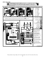
13
COM
TH
TR
DE
CAS
HUM
O
R
2
1
C
2
1
ST4
ST3
ST2
ST1
3A
C
Y2
24VAC
FUSE
W1
W2
R
C
G
W1
W2
Y1
3
2
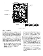
Dip Switches
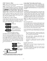
Green CFM LED
Seven Segment
LED
Auxiliary
Alarms
Communicating Board
C
IRCULATOR
B
LOWER
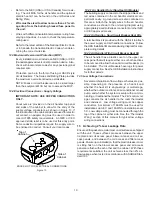
This air handler is equipped with a multi-speed circulator
blower. This blower provides ease in adjusting blower speeds.
The Specification Sheet applicable to your model provides an
airflow table, showing the relationship between airflow (CFM)
and external static pressure (E.S.P.), for the proper selection
of heating and cooling speeds. The heating blower speed
shipped is set at 21kW or 25kW, and the cooling blower speed
is set at “D”. These blower speeds should be adjusted by the
installer to match the installation requirements so as to pro-
vide the correct electric heating CFM and correct cooling CFM.
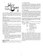
Use the CFM LED (green) to obtain an approximate airflow
quantity. The green CFM LED blinks once for each 100 CFM
of airflow.
1. Determine the tonnage of the cooling system installed
with the air handler. If the cooling capacity is in BTU/hr
divide it by 12,000 to convert capacity to TONs.
Example:
Cooling Capacity of 30,000 BTU/hr.
30,000/12,000 = 2.5 Tons
2. Determine the proper airflow for the cooling system.
Most cooling systems are designed to work with airflows
between 350 and 450 CFM per ton. Most manufactur-
ers recommend an airflow of about 400 CFM per ton.
Example:
2.5 tons X 400 CFM per ton = 1000 CFM
The cooling system manufacturer’s instructions must be
checked for required airflow. Any electronic air cleaners or
other devices may require a specific airflow; consult installa-
tion instructions of those devices for requirements.
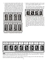
3. Knowing the air handler model, locate the high stage
cooling airflow charts in the Specification Sheet appli-
cable to your model. Look up the cooling airflow deter-
mined in step 2 and find the required cooling speed and
adjustment setting.
Example:
An AVPTC30C14 air handler installed with
a 2.5 ton air conditioning system. The airflow needed is
1000 CFM. Looking at the cooling speed chart for
AVPTC30C14, find the airflow closest to 1000 CFM. A
cooling airflow of 1000 CFM can be attained by setting
the cooling speed to “C” and the adjustment to “0” (no
adjustment).


